High-pressure slurry injector with quick ceramic forming and die releasing functions

A high-pressure grouting machine and molding die technology, which is applied to supply devices, manufacturing tools, etc., can solve the problems of affecting the surface quality of the mud billet, slow mud billet molding, and low pressure of the grouting system, so as to achieve good appearance quality and molding. Fast speed and stable pressure

Active Publication Date: 2014-05-14
HUBEI XISHUI KEMEI MACHINERY
View PDF6 Cites 12 Cited by
  • Summary
  • Abstract
  • Description
  • Claims
  • Application Information

AI Technical Summary

Problems solved by technology

[0003] The purpose of the present invention is to solve the problem that the existing high-pressure grouting machine uses a single cylinder to open and close the mold, and the precision of mold closing is poor, which affects the quality of the mud forming surface, the pressure is unstable and the pressure of the grouting system is small, which leads to the speed of mud forming. Slow, high water content of mud, low yield, poor product quality and other problems, to provide a rapid prototyping demoulding ceramic high-pressure grouting machine

Method used


Image

  • High-pressure slurry injector with quick ceramic forming and die releasing functions
  • High-pressure slurry injector with quick ceramic forming and die releasing functions

Examples


Embodiment Construction

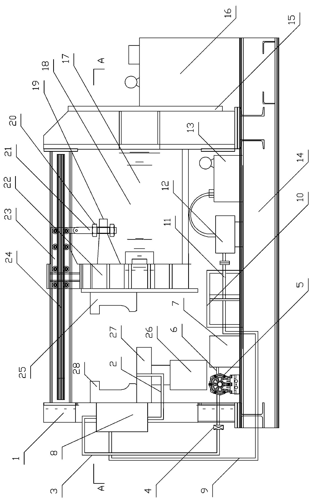
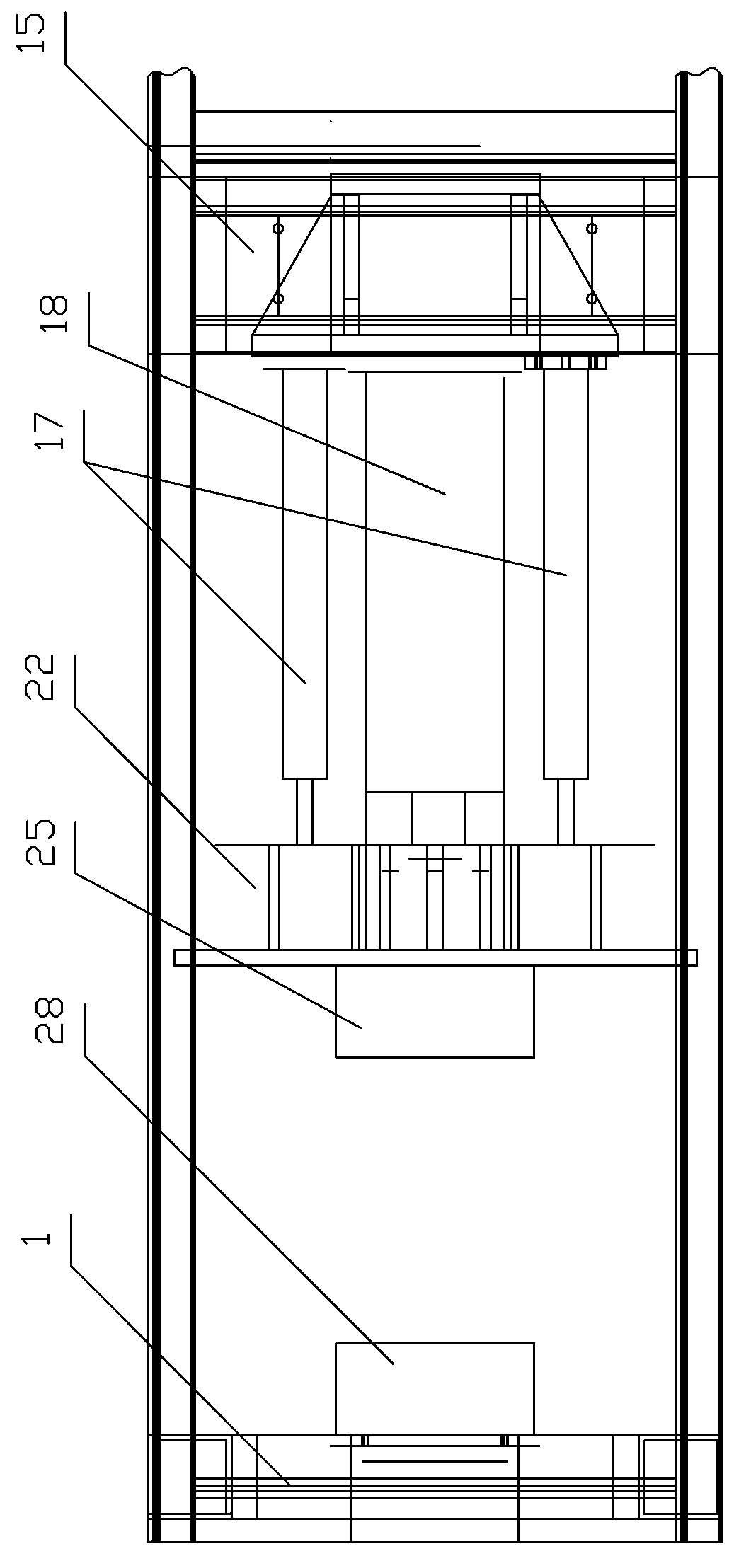
[0014] see figure 1 , 2 , the present invention has frame-shaped frame, and the top of frame 14 is provided with slide rail 24 and is equipped with slide seat 23, and die head 22 is hoisted on slide seat 23, and die head 22 and frame left side support 1 two relatives The right half and the left half ceramic forming molds 25 and 28 are correspondingly installed on the surface, and a bottom mold 27 and a lifting cylinder 26 are installed below the left half ceramic forming mold 28, and a grouting system is installed on the base 14 of the frame 14. And the hydraulic integrated pump station 16 is installed on the right side of the frame 14, especially: between the support 15 on the right side of the frame 14 and the die head 22, a pressurized main oil cylinder 18 and two auxiliary molds for opening and closing are connected. Oil cylinder 17, the grouting system includes a mud blank forming die, a pneumatic diaphragm pump 5 and a grouting pipe 2, the inlet end of the pneumatic dia...


PUM


Abstract

The invention discloses a high-pressure slurry injector with quick ceramic forming and diereleasing functions. The high-pressure slurry injector comprises a frame-shaped framework. A slide rail is arranged on the top of the framework, the framework is provided with a slide seat, a pressing die head is hoisted on the slide seat, a right half ceramic forming die and a left half ceramic forming die are respectively mounted on the pressing die head and a left-side support of the framework, a bottom die and a lifting cylinder are arranged below the left half ceramic forming die, a slurry injection system is mounted on a base of the framework, and a hydraulic integrated pump station is mounted on the right side of the framework. The high-pressure slurry injector is characterized in that a master pressurization cylinder and two auxiliary cylinders for opening and closing the dies are arranged between a right-side support of the framework and the pressing die head in a connected manner; the slurry injection system comprises a mud blank forming die, a pneumatic diaphragm pump and a slurry injection pipe, the forming dies are connected with one end of the slurry injection pipe, a high-pressure slurry storage tank is communicated with the other end of the slurry injection pipe, and an outlet of the pneumatic diaphragm pump is communicated with the high-pressure slurry storage tank via a slurry supply pipe B; the high-pressure slurry injector is provided with a pressurization device. The high-pressure slurry injector has the advantages that the dies can be closed accurately, the pressure is stable, the die releasing time is short, products are good in quality and high in qualified rate, and the high-pressure slurry injector is mainly used for manufacturing ceramic blanks.

Description

technical field [0001] The invention relates to ceramic production equipment, in particular to a high-pressure grouting machine for rapid prototyping and demoulding ceramics. Background technique [0002] At present, manual grouting is mainly used in domestic ceramic production and processing, which has low production efficiency, high labor intensity, and difficult to improve product quality. The high-pressure grouting machine mainly produced in Germany has successfully replaced manual grouting in the world, and this kind of grouting equipment has begun to be introduced in China. However, the structure of this equipment is very complicated, the cost is extremely high, and the purchase price is higher, and there are the following disadvantages: a single oil cylinder is used to open and close the mold and compress the mold, and the precision of mold closing is not high, which affects the molding surface quality of the mud blank. Pressure is limited and unstable. Especially d...

Claims


Application Information

Patent Timeline
Patent Type & Authority Applications(China)
IPC IPC(8): B28B13/02
CPCB28B13/021
Inventor 胡俊明
Owner HUBEI XISHUI KEMEI MACHINERY
Why Eureka
Try Eureka