Rotor head of rotary wing flying machine and method of manufacturing and assembling such rotor head

A technology of rotorcraft and rotorcraft, applied in aircraft, rotorcraft, transportation and packaging, etc., can solve the problems of air incapacity and flow, and achieve the effects of reducing fuel consumption, small production costs and tolerances

Active Publication Date: 2014-05-14
AIRBUS HELICOPTERS DEUT GMBH
View PDF11 Cites 3 Cited by
  • Summary
  • Abstract
  • Description
  • Claims
  • Application Information

AI Technical Summary

Problems solved by technology

A complex spring mechanism keeps the fairing components in contact with each other so that air cannot flow inside the fairing

Method used


Image

  • Rotor head of rotary wing flying machine and method of manufacturing and assembling such rotor head
  • Rotor head of rotary wing flying machine and method of manufacturing and assembling such rotor head
  • Rotor head of rotary wing flying machine and method of manufacturing and assembling such rotor head

Examples


Embodiment Construction

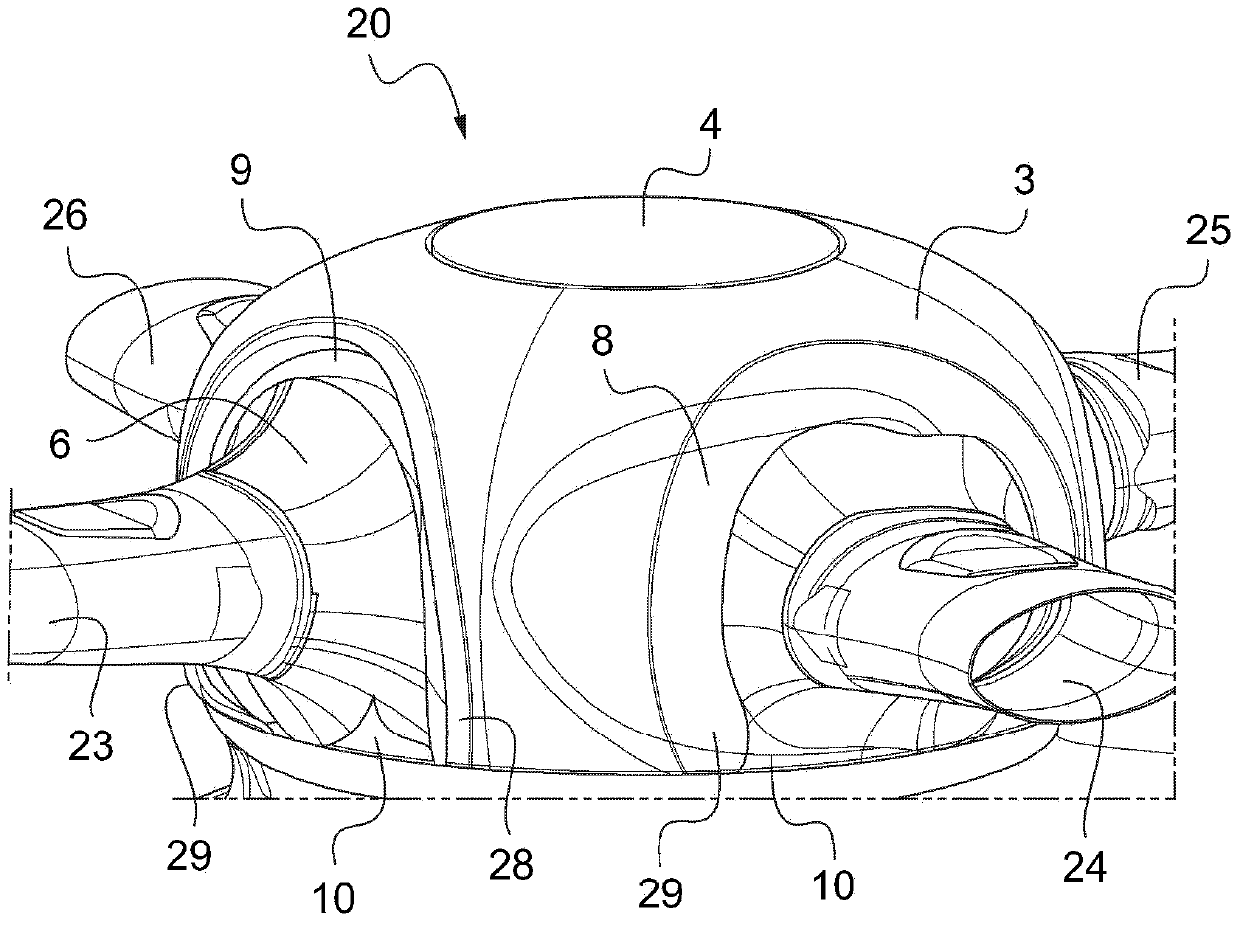
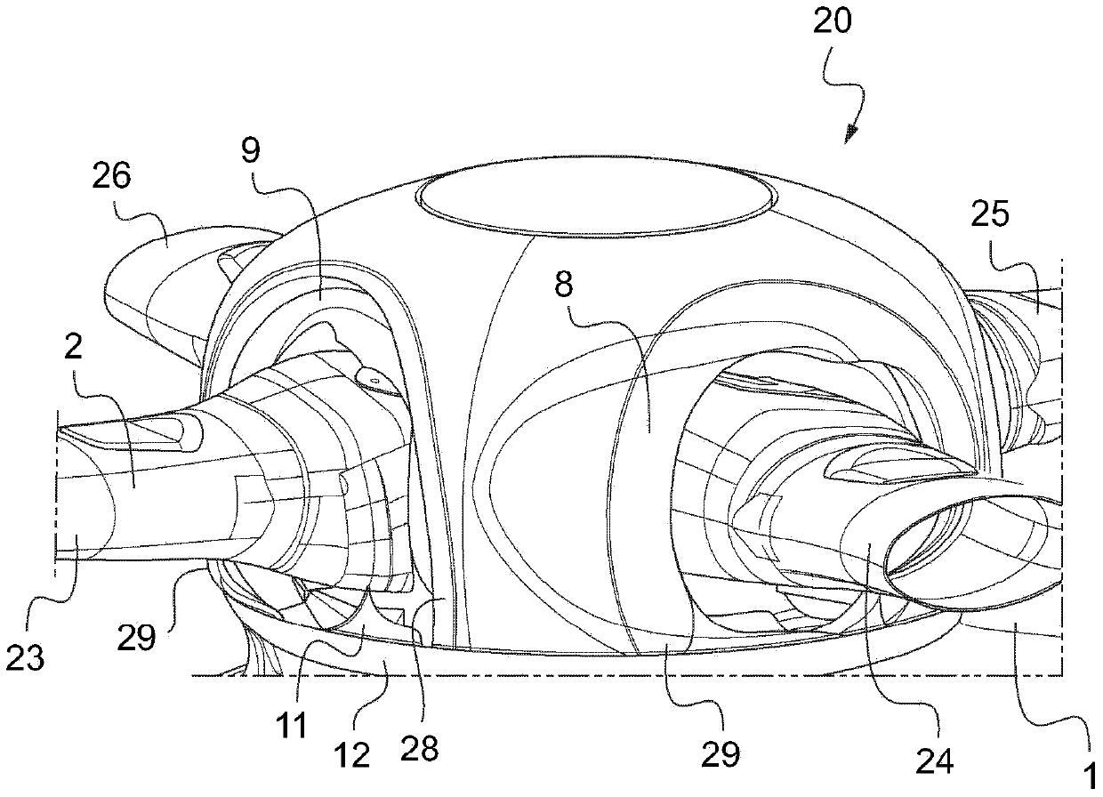
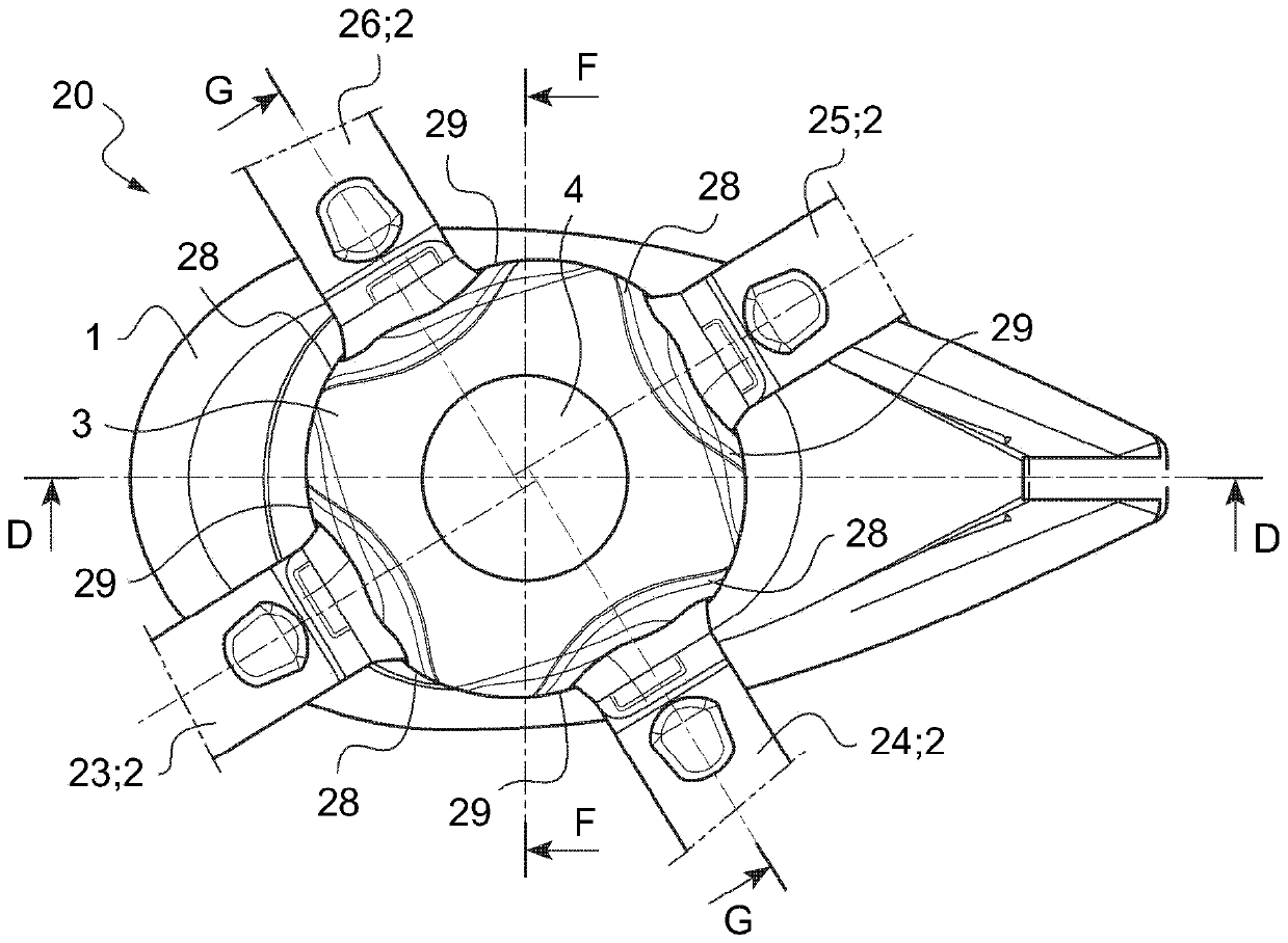
[0061] see Figure 1-4 , the rotor head 20 of the rotorcraft (not shown) is mounted on top of the fuselage (not shown). The rotor main shaft 21 or rotor shaft 22 extends upwards through the main shaft fairing 1 , above the fuselage and into the rotor head 20 . The non-rotating main shaft fairing 1 is provided with an upwardly directed main shaft fairing lip 12 which is coaxial with said rotor main shaft 21 or rotor shaft 22 . The main shaft fairing 1 is made of glass fiber reinforced plastic with a honeycomb core. The spindle fairing lip 12 is made of carbon fiber reinforced plastic.

[0062] The vertical plane is along the axis of the rotor main shaft 21 or rotor shaft 22 , while the orthogonal plane is perpendicular to the axis of said main shaft or shaft of the rotor head of the rotorcraft.

[0063] The four rotor blades 23 - 26 are radially mounted to the rotor main shaft 21 or rotor shaft 22 by means of separable blade attachments for rotation with the rotor head 20 . ...


PUM


Abstract

The invention relates to a rotor head (20) of a rotary wing flying machine with a fuselage, a rotor mast (21) or a rotor shaft (22) extending above said fuselage. A plurality of rotor blades (23-26) extend radial from said rotor mast (21) or rotor shaft (22) and means (2) for attaching said blades (23-26) to said rotor mast (21) or rotor shaft (22) permit flapping, pitch and lead-lag blade movements of said blades (23-26). A fairing / aerodynamically shaped hub-cap (3) encloses said rotor mast (21) or rotor shaft (22) and said blade attaching means (2). Said fairing / hub-cap (3) forms a chamber for said rotor mast (21) or rotor shaft (22) and has a peripheral cut-out for each blade (23-26) through which said blade (23-26) extends radial from said rotor mast (21) or rotor shaft (22). Said cut-outs are sized to accommodate all of the movements of said blades (23-26) with said blade attaching means (2) encountered in operation. The invention relates as well to a method of manufacturing and assembling the components of the inventive rotor head (20).

Description

technical field [0001] The invention relates to a rotor head for a rotorcraft having the features of claim 1 . The invention also relates to a method of manufacturing and assembling a rotor head of such a rotorcraft having the features of claim 11 . Background technique [0002] The high speed design of a helicopter with a streamlined fuselage and retractable landing gear can significantly increase the percentage contribution of the rotor hub and pylon to the total parasitic drag. [0003] Wagner.S.N. "Problems in Assessing Helicopter Drag" published on pages 5-1 to 5-12 of the AGARD (Aerospace Research and Development Advisory Group) Conference Proceedings No. 8, 1973 No. 124 A rotor head is disclosed which contributes 20-50% of the total helicopter depending on the fuselage design, i.e. with or without rear load carrying capacity, telescoping wheels or skids, dynamic or static air intakes resistance. [0004] Typically, the main shaft spinner covers the swash plate of t...

Claims


Application Information

Patent Timeline
IPC IPC(8): B64C27/32
CPCB64C7/00B64C27/32B64C27/04B64C27/54
Inventor A·德阿拉西奥S·莫雷斯U·德内克G·昆茨-费切纳D·施密克C·韦勒H-P·克拉姆
Owner AIRBUS HELICOPTERS DEUT GMBH
Why Eureka
Try Eureka