

Transmission shaft with real-time online torque monitoring device
A torque device and transmission shaft technology, applied in the field of transmission shafts, can solve the problems of high power supply environment requirements, sliding wear, limited electric energy, etc., and achieve the effect of stable and reliable working performance and high measurement accuracy
- Summary
- Abstract
- Description
- Claims
- Application Information
AI Technical Summary
Problems solved by technology
Method used
Image

Examples
Embodiment Construction
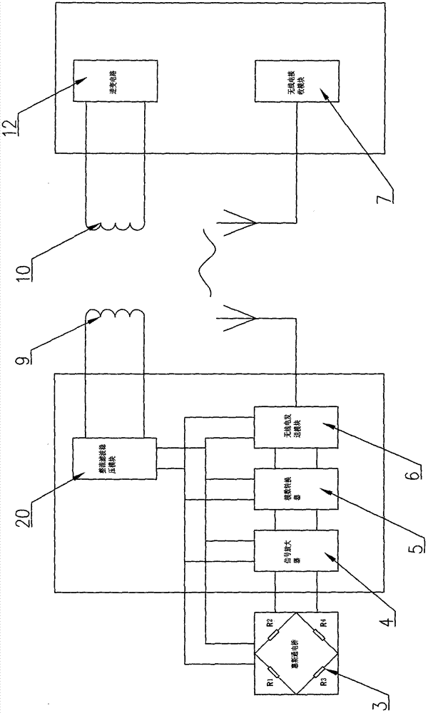
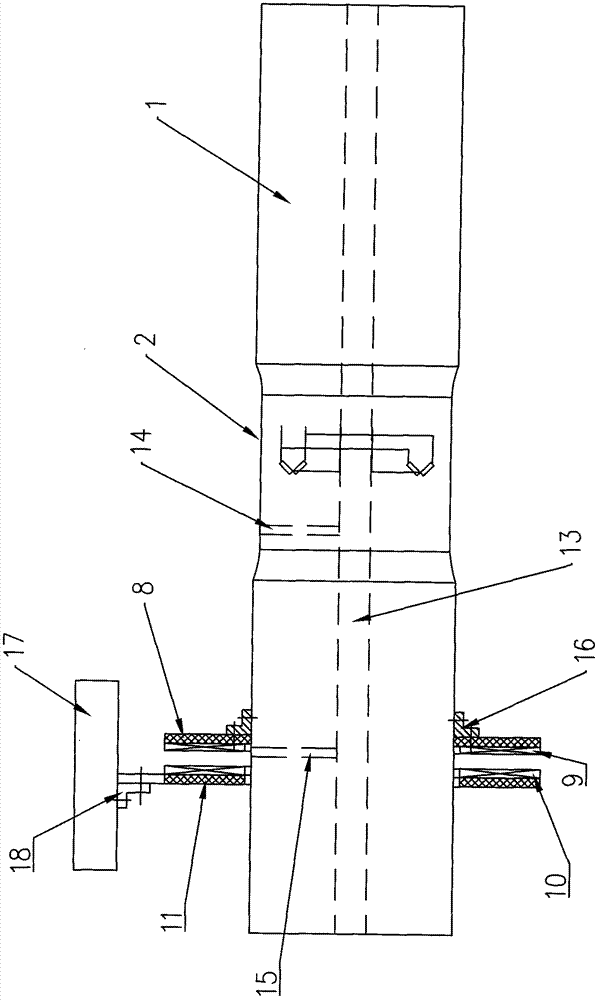
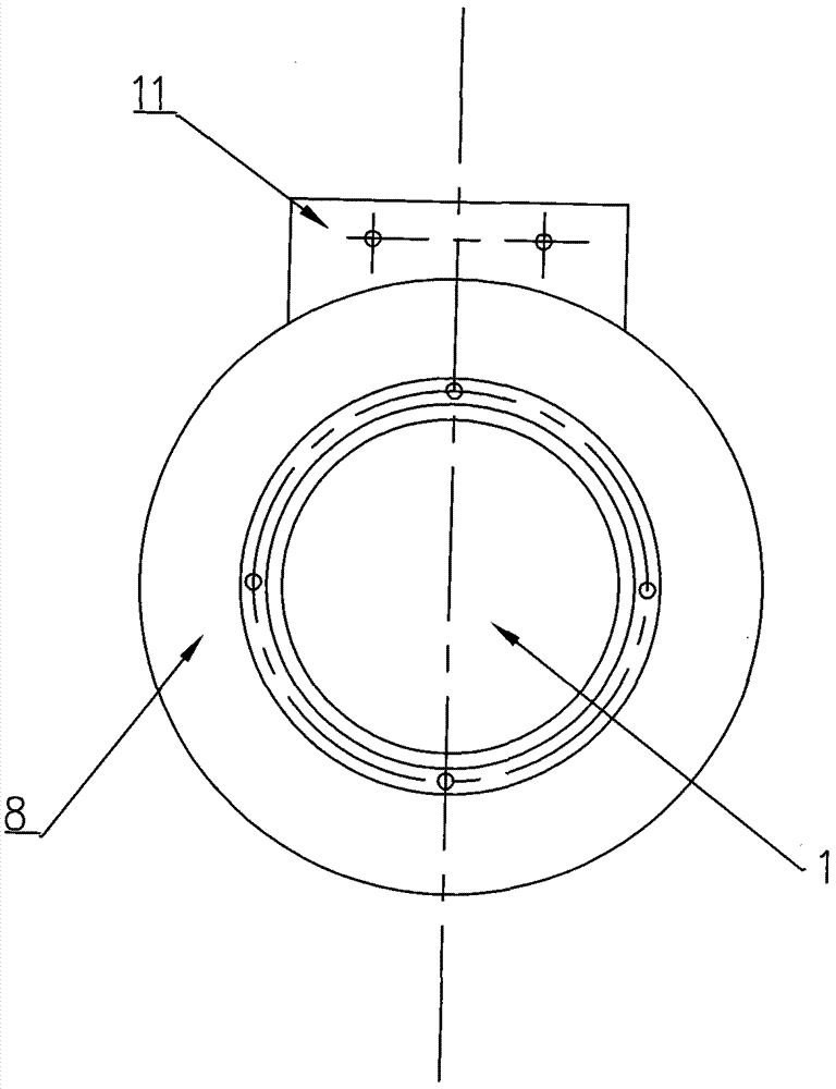
[0022] like figure 1 , figure 2 and image 3 As shown, the transmission shaft with a real-time on-line monitoring torque device of the present invention includes a shaft 1, and the middle part of the side wall of the shaft 1 is provided with an installation groove 2 for installing electrical components, and the installation groove 2 is for surrounding the side of the shaft 1 The circular ring of the wall is provided with a Wheatstone bridge 3 including metal resistance strain gauges in the installation groove 2, and the two half-bridge strain gauges of the Wheatstone bridge 3 are respectively attached to the bottom of the installation groove 2 axially symmetrically. Each half-bridge strain gauge includes two resistance strain gauges respectively, the electrical signal output end of the Wheatstone bridge 3 is electrically connected to the electrical signal input end of the signal amplifier 4, and the electrical signal output end of the signal amplifier 4 is connected to the a...
PUM
| Property | Measurement | Unit |
|---|---|---|
| Depth | aaaaa | aaaaa |
| Length | aaaaa | aaaaa |
Abstract
Description
Claims
Application Information