Charged spray catalytic micro burner

A micro-combustion and charging technology, which is applied in the direction of burners, lighting and heating equipment, etc., can solve the problems of temperature drop in flame stable area, influence on fuel stability, increase of heat loss, etc., so as to reduce ignition temperature, promote sufficiency and Stability, heat loss reduction effect

Inactive Publication Date: 2014-05-14
SOUTH CHINA UNIV OF TECH
View PDF3 Cites 5 Cited by
  • Summary
  • Abstract
  • Description
  • Claims
  • Application Information

AI Technical Summary

Problems solved by technology

At the same time, as the size of micro-scale combustion is smaller than that of traditional combustion, many technical difficulties have arisen
For example, the ratio of the surface area to the volume of the micro burner is much larger than that of the traditional burner, which increases the heat loss and reduces the temperature in the flame stable area, which is easy to cause the flame to go out and affect the stability of the fuel ignition.

Method used


Image

  • Charged spray catalytic micro burner
  • Charged spray catalytic micro burner
  • Charged spray catalytic micro burner

Examples


Embodiment Construction

[0025] The present invention will be described in further detail below in conjunction with specific embodiments.

[0026] Implementation example

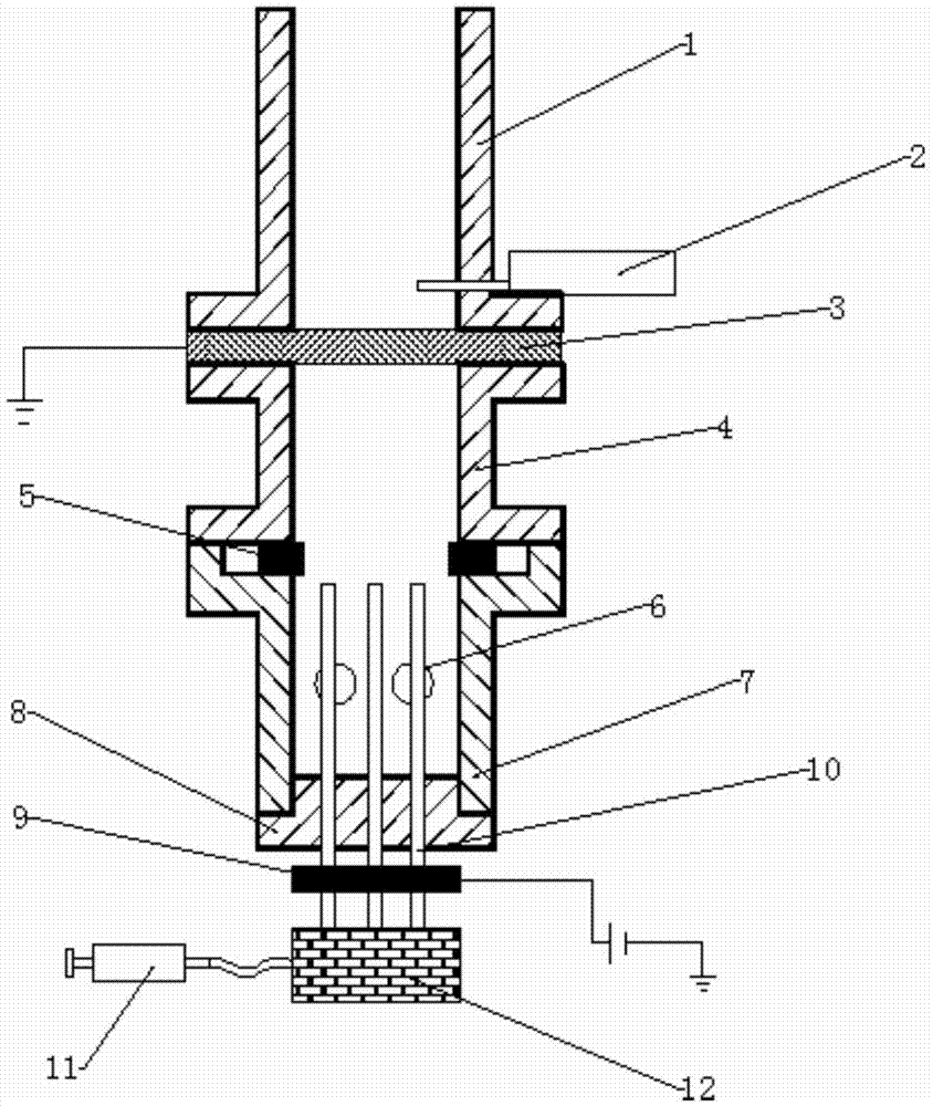
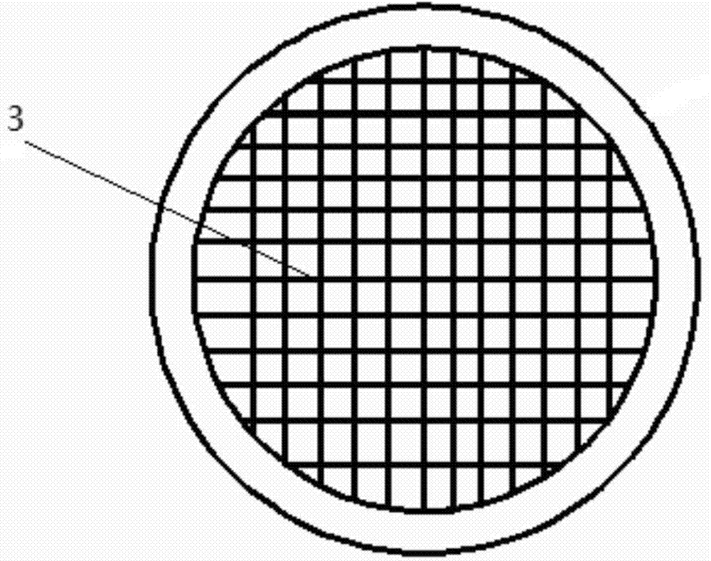
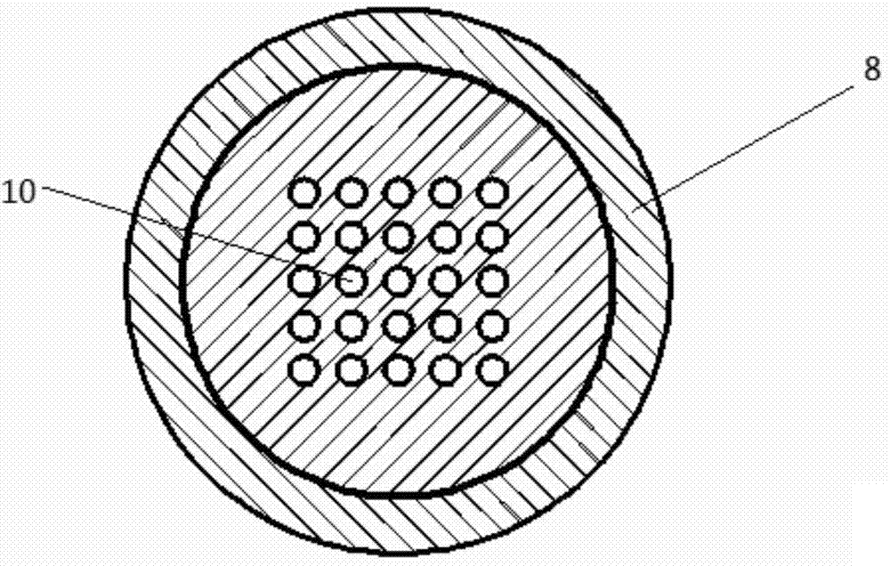
[0027] Such as Figure 1 to Figure 3 shown. The charged spray catalytic micro-combustor of the present invention includes an upper cylinder 1, a middle cylinder 4, a lower cylinder 7, an igniter 2, and a nozzle fixing plug 8, and a grid with a catalyst layer is arranged between the upper cylinder 1 and the middle cylinder 4 3. The ignition needle of the igniter 2 penetrates the wall of the upper cylinder 1 and is placed above the grid in the upper cylinder 1; a ring electrode 5 is set between the middle cylinder 4 and the lower cylinder 7, and a spray nozzle is installed at the outlet of the lower cylinder 7. Pipe fixing plug 8; multiple liquid fuel nozzles 10 are fixed on the nozzle fixing plug 8 .

[0028] The liquid fuel nozzle 10 is connected to the positive pole of a high-voltage DC power supply (the voltage of the DC power ...


PUM


Abstract

The invention discloses a charged spray catalytic micro burner which mainly comprises an upper barrel, a middle barrel, a lower barrel and an igniter. Liquid fuel spay pipes are arranged in the lower barrel, a catalytic combustion gird coated with catalysts in a spraying mode is arranged between the upper barrel and the middle barrel, and an ignition needle of the igniter penetrates through the wall face of the upper barrel, and is arranged above a grid inside the upper barrel. An annular electrode is arranged between the middle barrel and the lower barrel, and a highfield area is formed between the grid and the annular electrode. A spray pipe fixing plug is arranged below the lower barrel, and the spray pipes are fixed to the plug. According to the characteristic of liquid fuel combustion under a microscale condition, the double-electrode structure is designed, the annular electrode is combined with spray pipe electrodes, a charged spray technology is combined with a catalytic combustion technology, and the multiplexing spray pipes are designed. Efficient, stable and low-pollution combustion of the liquid fuel can be achieved under the microscale condition, the aim of controlling the complex combustion process can be achieved by adjusting voltages and other simple electric field parameters, and theoretical innovativeness is achieved.

Description

technical field [0001] The invention relates to a miniature liquid fuel burner, in particular to a charge-spray catalytic micro-combustor. Background technique [0002] With the rapid development of MEMS technology, micro-energy systems have become a research hotspot today. Combustion-based micro-energy systems have the characteristics of high energy density (about 20 to 75 times that of conventional batteries) and small combustion scales (generally mm and μm levels). The performance of its core component, the micro-combustor, needs to be improved urgently, which has become a bottleneck for the further development of the micro-energy system. [0003] At present, the research on micro-scale combustion at home and abroad mostly focuses on the premixed combustion or catalytic combustion of gaseous fuels, while the research on the combustion of liquid fuels is less. Compared with gaseous fuels, liquid fuels have the advantages of easy storage and transportation, high energy de...

Claims


Application Information

Patent Timeline
IPC IPC(8): F23D11/32F23D11/36F23D11/38
Inventor 甘云华佟洋
Owner SOUTH CHINA UNIV OF TECH
Why Eureka
Try Eureka