Thermal expansion valve with unidirectional control function

A thermal expansion valve and one-way control technology, applied in the field of thermal expansion valves, can solve problems such as product reliability decline, complex structure, expansion valve leakage, etc., achieve simple and reliable installation, improve product manufacturability, and reduce external leakage hidden effect

Active Publication Date: 2014-05-14
ZHEJIANG SANHUA CLIMATE & APPLIANCE CONTROLS GRP CO LTD
View PDF6 Cites 8 Cited by
  • Summary
  • Abstract
  • Description
  • Claims
  • Application Information

AI Technical Summary

Problems solved by technology

[0005] Apparently, although the above-mentioned structure can integrate a single expansion valve and a one-way valve into an integrated structure, since it is necessary to process an opening on the valve body to install a nut cover and install a one-way valve device, it is easy to cause leakage of the expansion valve. directly lead to a decrease in the reliability of the product
In addition, this structure is complex and requires high processing technology

Method used


Image

  • Thermal expansion valve with unidirectional control function
  • Thermal expansion valve with unidirectional control function
  • Thermal expansion valve with unidirectional control function

Examples


Embodiment 1

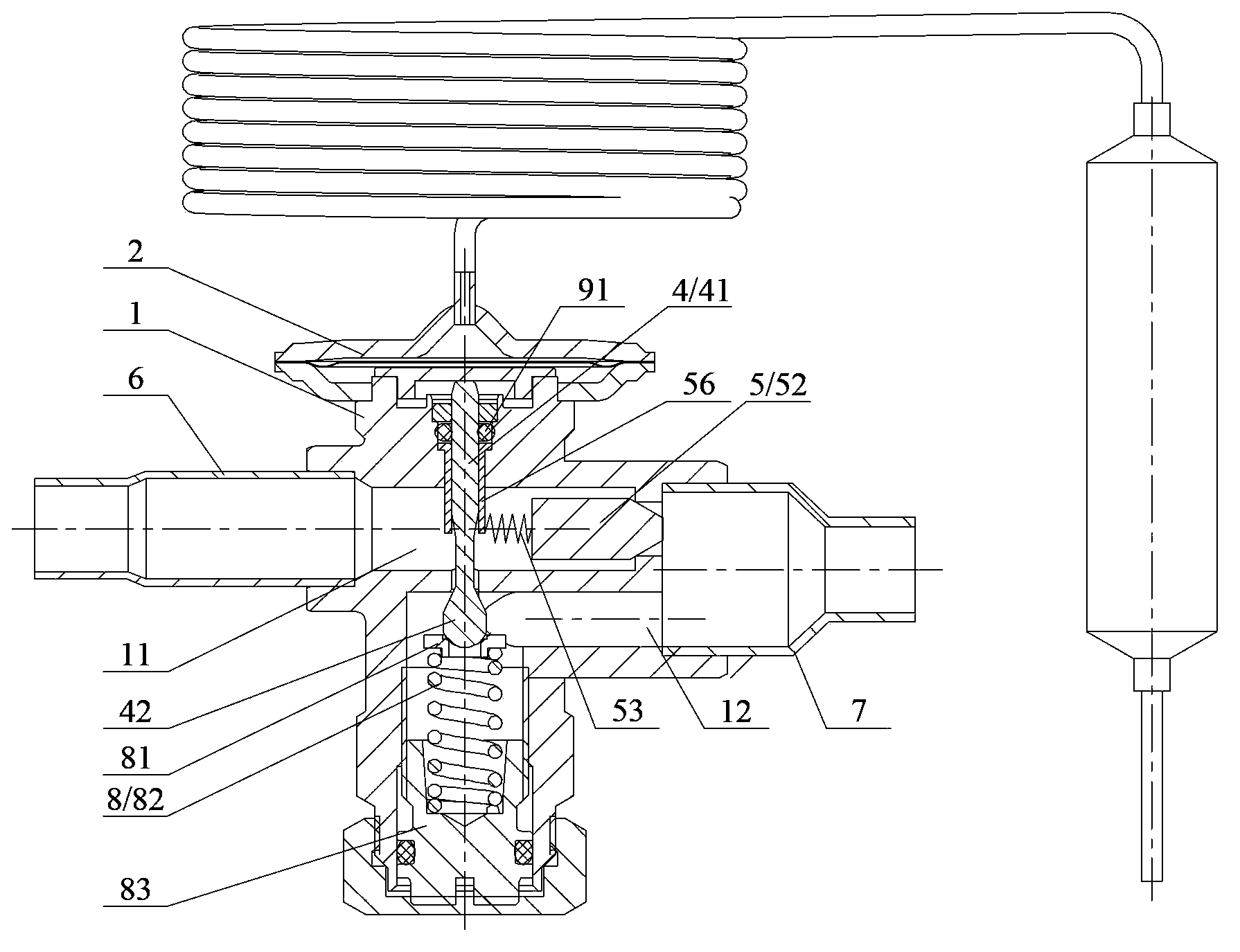
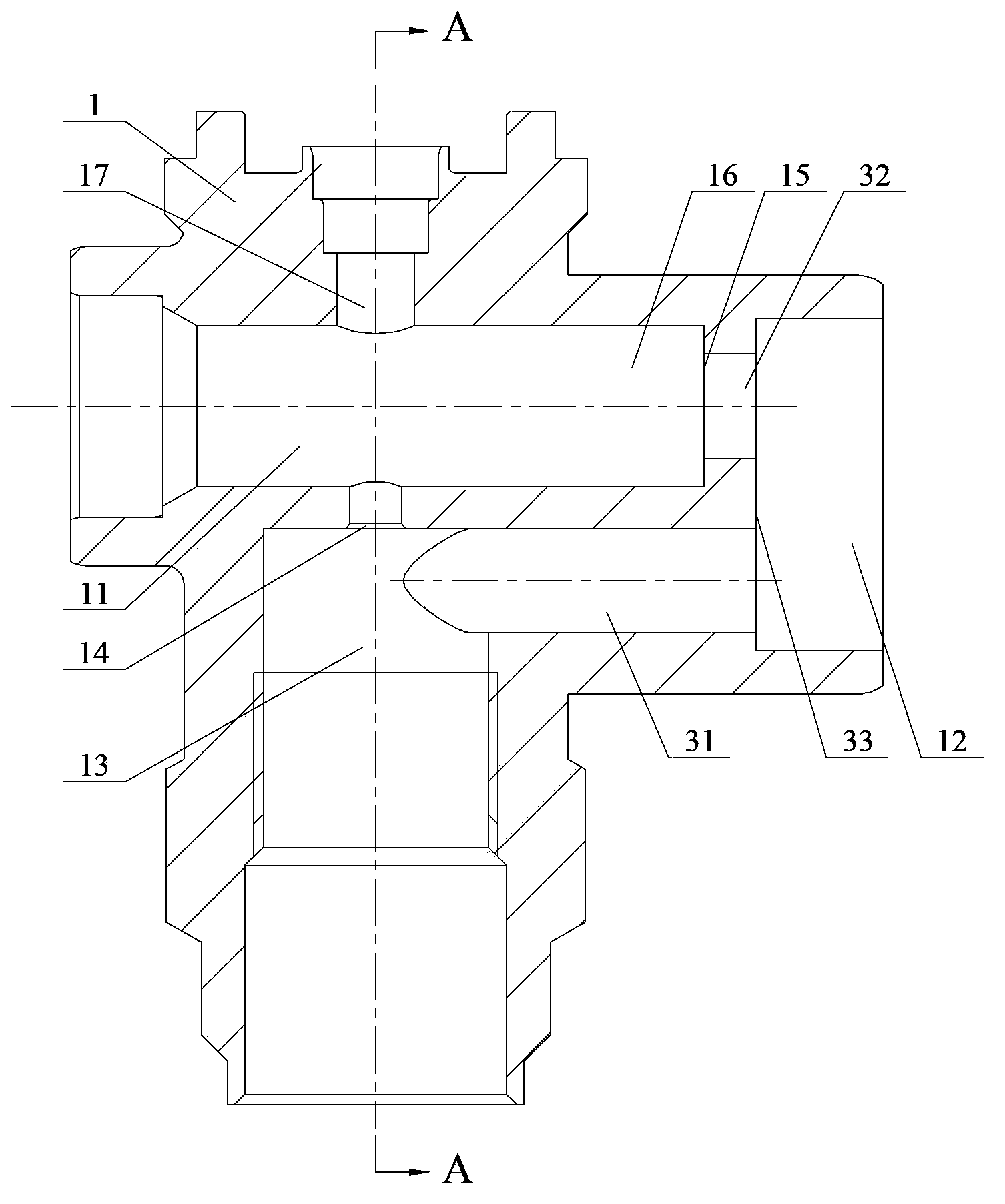
[0033] See figure 2 and image 3 ,in, figure 2 It is a structural schematic diagram of the thermal expansion valve with one-way control function described in the first embodiment, image 3 Yes figure 2 Schematic diagram of the valve body structure of the thermal expansion valve described in .

[0034] like figure 2 and image 3 shown. In this embodiment, the thermal expansion valve includes a valve body 1, on which an inlet channel 11 and an outlet channel 12 are arranged, and an inner cavity 13 communicating with the inlet channel 11 and the outlet channel 12 is processed in the valve body 1, The temperature sensing component 2 is placed at one end of the valve body 1 . The inner cavity 13 of the valve body 1 also includes a vertical through hole 17 communicating with the temperature sensing component 2 , the lower part of the hole 17 intersects with the inner cavity 13 to form a first valve port 14 .

[0035] The first valve core part 4 is provided through the th...

Embodiment 2

[0050] Compared with the first embodiment, this embodiment has the same main body composition and connection relationship. The difference is that in this solution, a further positioning function is added to the inner end of the limiting sleeve 56 .

[0051] Please also see Image 6 and Figure 7 ,in, Image 6 It is a structural schematic diagram of the thermal expansion valve with one-way control function described in the second embodiment; Figure 7 Yes Image 6 Schematic diagram of the limit sleeve structure of the thermal expansion valve shown in . In order to clearly show the difference between this solution and the first embodiment, components and structures with the same function are marked with the same reference numerals.

[0052] like Image 6 and Figure 7 As shown, opposite to the hole 17 in the axial direction, the valve body 1 above the first valve port 14 is provided with a positioning stop 1931 for accommodating the inner extension end of the limit sleeve...

Embodiment 3

[0056] Compared with the second embodiment, this embodiment has the same main structure and connection relationship. The difference is that this solution is aimed at different positioning structures of the inner end of the limiting sleeve 56 .

[0057] Please also see Figure 8 and Figure 9 ,in, Figure 8 It is a structural schematic diagram of the thermal expansion valve with one-way control function described in the third embodiment; Figure 9 Yes Figure 8 Schematic diagram of the limit sleeve structure of the thermal expansion valve shown in . In order to clearly show the difference between this solution and the first and second embodiments, components and structures with the same function are marked with the same reference numerals.

[0058] like Figure 8 and Figure 9 As shown, opposite to the hole 17 in the axial direction, the valve body 1 at the first valve port 14 is provided with an insertion hole 1932 for accommodating the inner extension end of the limit ...


PUM


Abstract

The invention discloses a thermal expansion valve with a unidirectional control function. The thermal expansion valve comprises a valve body having an inlet passage and an outlet passage, a temperature sensing part disposed at one end of the valve body, and a first spool part disposed in an inner cavity of the valve body. The first spool part comprises a valve stem and a first spool; the valve stem is abutted to the temperature sensing part; the first spool coordinates with a first valve port in the inner cavity to control the quantity of medium fluid flowing from the inlet passage to the outlet passage. The valve body further comprises an accommodating portion extending from the inlet passage to the inside of the valve body. The accommodating portion is provided with a second valve port and an internal second spool part. A limit bushing is arranged between the valve stem and the valve body in a sleeving manner. The limit bushing inwardly extends into the accommodating portion to limit the opening position of the second spool part. When the medium flows from the inlet passage to the outlet passage, the second valve port is closed; when the medium flows from the outlet passage to the inlet passage, the second valve port is open. Compared with the prior art, the thermal expansion valve has the advantages that operational reliability is effectively improved on the premise of improving manufacturability.

Description

technical field [0001] The invention relates to the technical field of refrigeration components, in particular to a thermal expansion valve with a one-way control function. Background technique [0002] The thermal expansion valve as a throttling device is widely used in the circuit of the refrigeration system to control the flow of the refrigerant by sensing the temperature and pressure of the refrigerant at a specific location; with the continuous promotion of commercial refrigeration equipment, the thermal expansion valve is used in commercial It is also widely used in large capacity refrigeration systems. [0003] In the prior art, if the evaporator and condenser are far away from the compressor pipeline in the refrigeration system (greater than 25 meters), the thermal expansion valve is realized by connecting a check valve in parallel (the direction is opposite to that of the expansion valve). , to improve system stability. The flow direction of the one-way valve is o...

Claims


Application Information

Patent Timeline
Patent Type & Authority Applications(China)
IPC IPC(8): F25B41/06F16K31/64F16K15/02F25B41/31
Inventor 不公告发明人
Owner ZHEJIANG SANHUA CLIMATE & APPLIANCE CONTROLS GRP CO LTD
Why Eureka
Try Eureka