
Wood nondestructive testing device capable of conducting imaging in real time at any angle

A non-destructive testing and real-time imaging technology, applied in the direction of using radiation for material analysis, etc., can solve the problems that the detection device cannot realize the detection of the measured object at any angle, the image acquisition is not timely and inconsistent, and the image acquisition time is long. Improve, reduce human operation, and improve the efficiency of image acquisition

Inactive Publication Date: 2014-05-14
NORTHEAST FORESTRY UNIVERSITY
View PDF9 Cites 18 Cited by
  • Summary
  • Abstract
  • Description
  • Claims
  • Application Information

AI Technical Summary

Problems solved by technology

[0005] The purpose of the present invention is to solve the problem that the existing detection device cannot detect any angle of the measured object, and usually only detects objects in a two-dimensional plane, and there are problems such as long image acquisition time and poor clarity, and the acquisition of images is not timely and incoherent problem, and then provide a wood non-destructive testing device with real-time imaging at any angle

Method used


Image

  • Wood nondestructive testing device capable of conducting imaging in real time at any angle
  • Wood nondestructive testing device capable of conducting imaging in real time at any angle
  • Wood nondestructive testing device capable of conducting imaging in real time at any angle

Examples


specific Embodiment approach 1

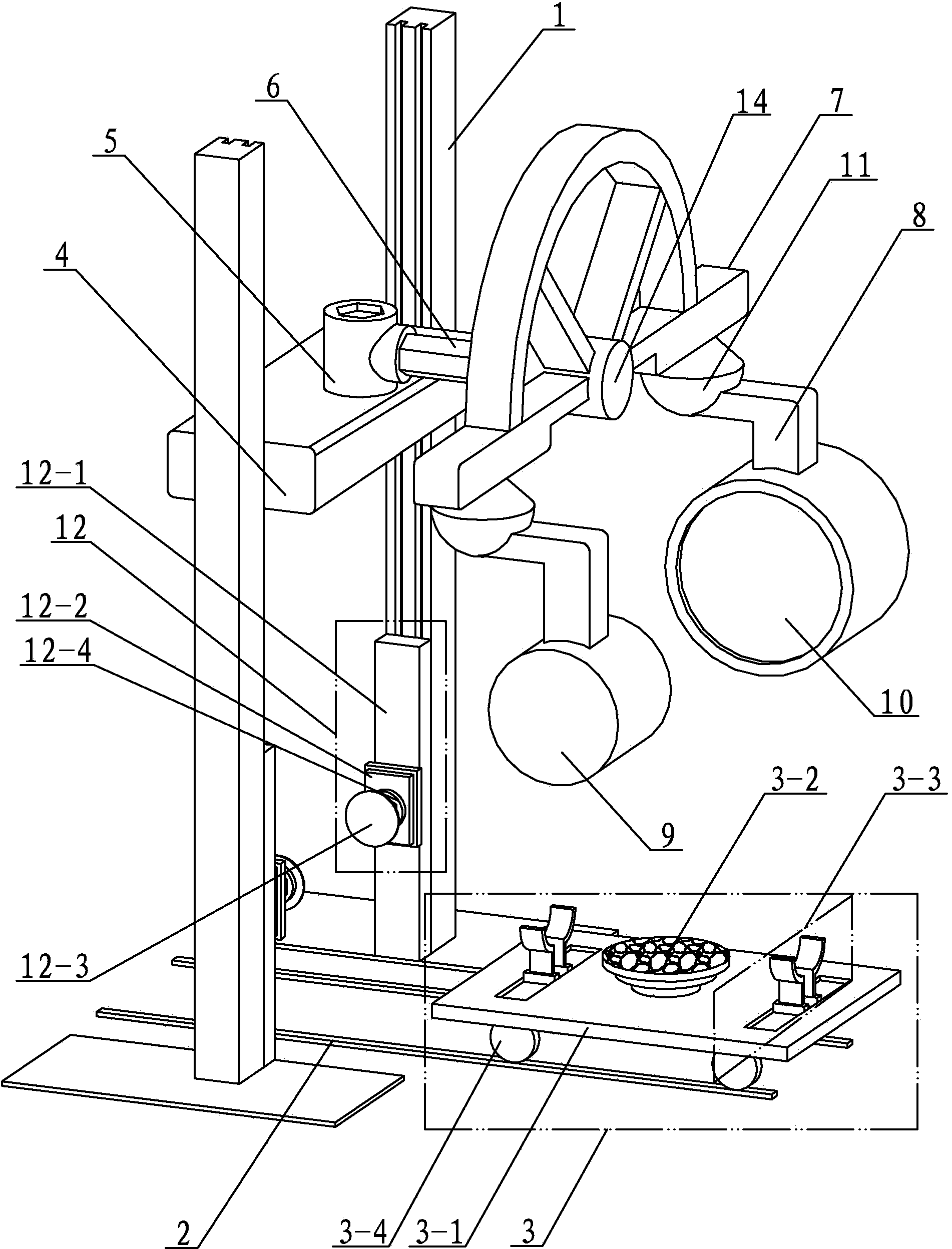
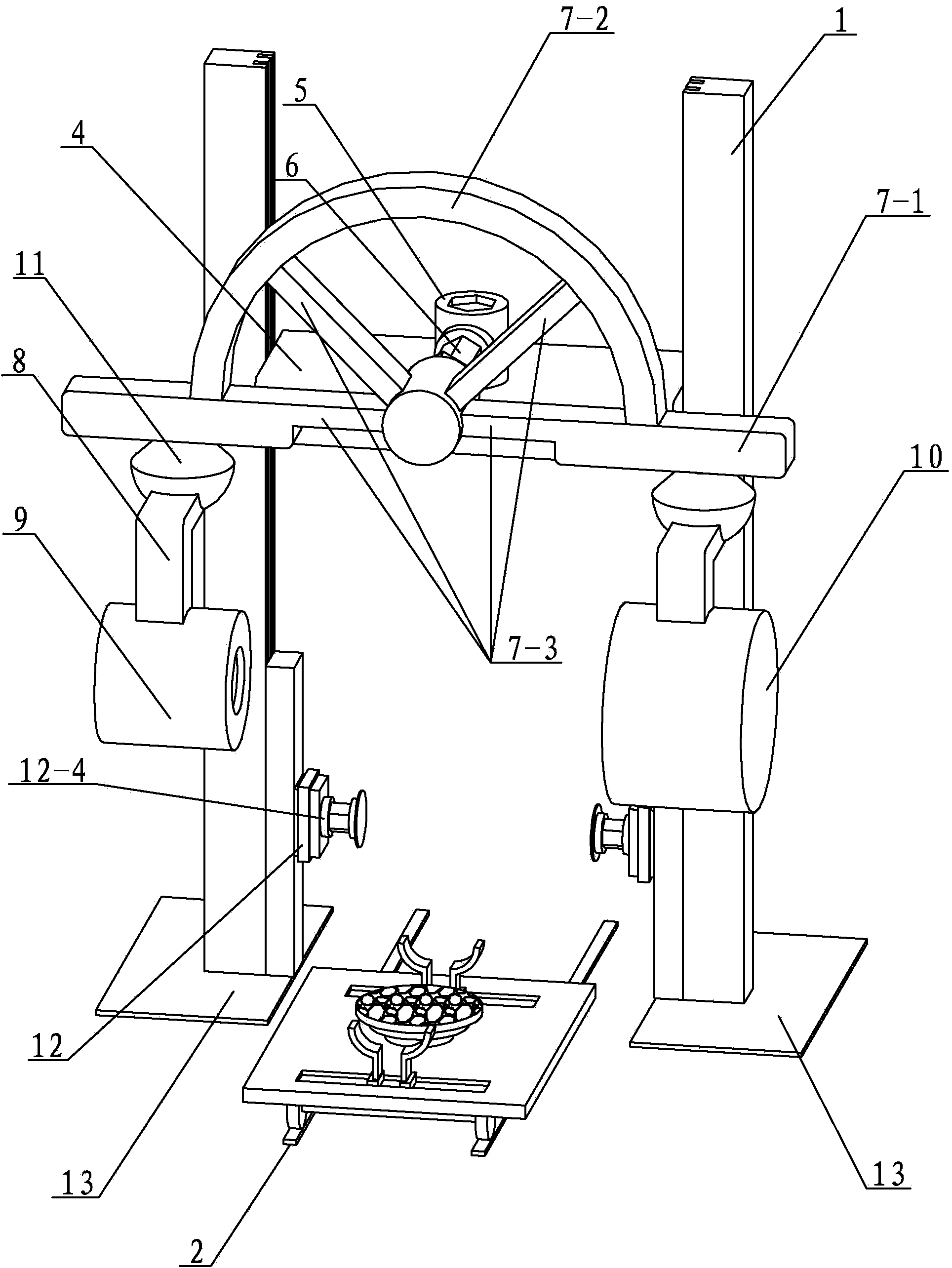
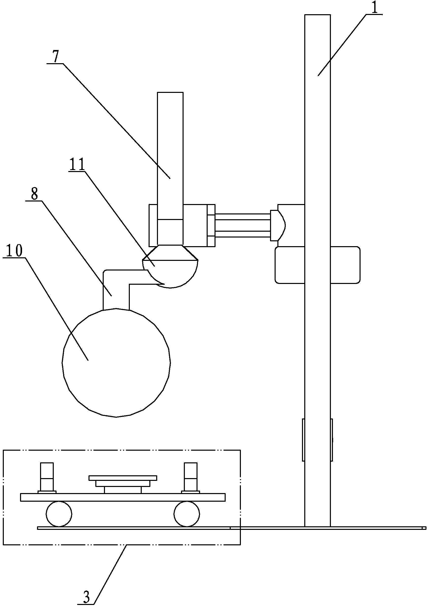
[0018] Specific implementation mode one: combine Figure 1-Figure 5 Describe this embodiment, a wood non-destructive testing device with real-time imaging at any angle in this embodiment, which includes a slide rail 2, a loading vehicle 3 and two brackets 1, the two brackets 1 are vertically arranged side by side, and the slide rail 2 is located on the Between the two brackets 1, and perpendicular to the two brackets 1, the loading cart 3 can be slidably arranged on the slide rail 2, and the wood non-destructive testing device also includes a radially moving slide plate 4, a swing connecting block 5, an extension arm 6. Support arm 7, rotation adjustment motor 14, ray emitter 9, receiver 10, two poles 8 and two movable joints 11, the radially movable slide plate 4 can be slidably arranged on the inner side walls of the two brackets 1 Above, the swing connection block 5 is fixedly installed on the radially moving slide plate 4, one end of the extension arm 6 is connected with t...

specific Embodiment approach 2

[0022] Specific implementation mode two: combination figure 1 and figure 2 To illustrate this embodiment, the wood non-destructive testing device of this embodiment further includes two mechanical claws 12 , and the two mechanical claws 12 are respectively slidably arranged at the lower parts of the inner side walls of the two brackets 1 . With such arrangement, the manipulator can clamp and rotate the object to change the position of the object to be detected relative to the loading vehicle, so as to realize all-round detection of the object to be detected. Unnecessary manual operations in this process can be reduced, radiation hazards to operators can be avoided, and detection efficiency can also be improved. Other compositions and connections are the same as in the first embodiment.

specific Embodiment approach 3

[0023] Specific implementation mode three: combination figure 1 and figure 2 Describe this embodiment, each mechanical jaw 12 of this embodiment all comprises clamping slider 12-1, hydraulic cylinder 12-2, clamping rotating motor 12-4 and clamping end 12-3, clamping slider 12 -1 is slidably arranged on the lower part of a support 1, the hydraulic cylinder 12-2 is fixedly arranged on the clamping slider 12-1, and the clamping end 12-3 is arranged on the hydraulic cylinder 12-1 by clamping the rotating motor 12-4. 2 front end. With such arrangement, it is convenient to realize the clamping and rotation of the article. Other compositions and connections are the same as those in the second embodiment.


PUM


Abstract

The invention discloses a wood nondestructive testing device capable of conducting imaging in real time at any angle to solve the problems that due to the fact that an existing testing device can not test a tested object at any angle and can usually test the object only in the two-dimensional plane, time for collecting images is long, definition is low, and the images can not be timely and coherently obtained, and relates to a wood testing device. According to the wood nondestructive testing device, two supports are vertically arranged in parallel, a slide rail is located between the two supports, a loading trolley is arranged on the slide rail in a slidable mode, radial moving sliding plates are arranged on the inner side walls of the two supports in a slidable mode, a swing adjusting motor is fixedly installed on the radial moving sliding plates, one end of an extension arm is connected with the swing adjusting motor, the other end of the extension arm is connected with a supporting arm through a rotating adjusting motor, the two ends of the supporting arm are respectively connected with a movable hinged joint, and a supporting rod is arranged on each hinged joint, and a ray transmitter and a receiver are fixedly arranged at the lower ends of the supporting rods respectively. The wood nondestructive testing device is used for testing wood.

Description

technical field [0001] The invention relates to a wood detection device, in particular to a wood non-destructive detection device with real-time imaging at any angle. Background technique [0002] Wood non-destructive testing technology is a new and comprehensive non-destructive testing technology of wood. It has developed rapidly in the past ten years. The traditional physical and mechanical properties of wood are mostly tested by testing instruments or mechanical testing machines for size, specification, The surface shape or the maximum load it can withstand is tested. This method has long detection time, harsh conditions, poor stability and reproducibility, and is not suitable for non-destructive, online rapid detection. Non-destructive testing of the physical and mechanical properties of wood or wood materials can quickly detect the interior of wood or wood materials by using today's physical methods and means without destroying the shape, original structure and origina...

Claims


Application Information

Patent Timeline
Patent Type & Authority Applications(China)
IPC IPC(8): G01N23/04
Inventor 戚大伟
Owner NORTHEAST FORESTRY UNIVERSITY
Learn More