
Method for measuring melting rate of covering slag

A melting rate and mold flux technology, applied in the field of mold flux performance measurement, can solve problems such as poor test reproducibility, errors, and laboratory failure to meet test conditions, improve test repeatability, reduce test costs, Quick and easy operation

Active Publication Date: 2014-05-14
HENAN TONGYU METALLURGY MATERIALS GRP
View PDF8 Cites 3 Cited by
  • Summary
  • Abstract
  • Description
  • Claims
  • Application Information

AI Technical Summary

Problems solved by technology

This method is also to overcome the shortcoming that the end point of melting needs human judgment, but in this method, there are the following defects: ①It is troublesome to separate the molten part from the cooled mold flux; ②Separate the condensed glass slag by screening, these glass The slag is easy to be mixed with unmelted mold slag in the process of condensation and separation, and the unmelted mold slag is easy to mix with small-sized glass slag, which is easy to cause large errors; ③ Since the mold slag in the crucible is almost completely melted , the end point of each record is different, resulting in a different error size each time, the test reproducibility is not good, and the influence caused by the error cannot be overcome through multiple tests
Compared with the error caused by human judgment of the end point in the prior art, the error caused by this method is larger
[0005] Patent Application No. 200410018064.0 "Detection Method for Mold Flux Melting Speed" reflects the melting speed of mold flux by detecting the burning of free carbon in the mold flux. The balance data is sampled by computer, which is not available in many laboratories. Such test conditions
The patent application number 200610023413.7 "A Method and Device for Measuring the Melting Speed ​​of Mold Flux" uses a resistance measuring instrument to take the constant resistance of mold slag as the measurement end point, which is easier to implement than the method of detecting free carbon, but this The method also needs to purchase the instrument to realize the determination

Method used


Image

  • Method for measuring melting rate of covering slag
  • Method for measuring melting rate of covering slag
  • Method for measuring melting rate of covering slag

Examples


Embodiment 1

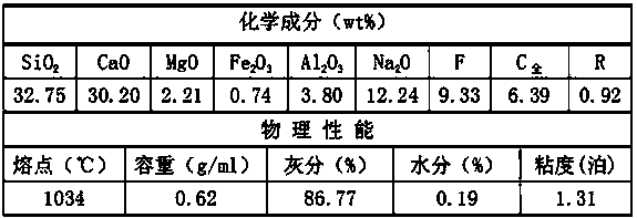
[0026] Take mold flux sample A, its chemical composition and physical properties are as follows:

[0027]

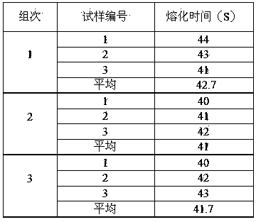
[0028] Divide the mold flux sample into three groups, and use the above-mentioned specific measurement steps to measure the melting speed of the three samples in each group and calculate the average value of each group. The melting speed is shown in the following table:

[0029]

Embodiment 2

[0031] Take mold flux sample B, its chemical composition and physical properties are as follows:

[0032]

[0033] Divide the mold flux sample into three groups, and use the above-mentioned specific measurement steps to measure the melting speed of the three samples in each group and calculate the average value of each group. The melting speed is shown in the following table:

[0034]

[0035] It can be obtained from the repeated test results of mold slag. This method of testing the melting speed of continuous casting mold slag is simple, has good reproducibility, and has high reliability of test results.


PUM


Abstract

The invention discloses a method for measuring the melting rate of covering slag. According to the method, the molten covering slag is absorbed by utilizing magnesite, a measuring end-point is determined based on the complete melting absorption of the covering slag, and the melting rate is judged according to the time period needed from putting of a covering slag sample to complete melting of the sample. The detection end-point time is not needed to be judged according to the melting shape of the covering slag, the influence of subjective factors in a previous slag column test method is overcome, the test phenomenon is intuitive, and the reproducibility is obviously improved. Moreover, the melting rate of the covering slag can be directly and accurately tested without calculation, the operation is rapid and convenient, instruments are not needed to be purchased additionally, a ceramic square boat filled with the magnesite can be repeatedly used, the detection material is saved, and the test cost is reduced.

Description

technical field [0001] The invention belongs to the technical field of measuring the performance of mold slag, and in particular relates to a method for measuring the melting speed of mold slag. Background technique [0002] The melting rate is one of the important properties of the mold flux, which determines the melting model structure formed by the mold flux on the molten steel surface in the mold. Through the measurement and analysis of the melting rate of the mold flux, the melting characteristics of the mold flux can be judged. The test methods used are: Seg cone test method, crucible test method, droplet test method, slag column test method, etc. These methods have certain limitations in practical application. Due to different test methods, the measurement results are often very different. By analyzing the characteristics and limitations of various existing melting speed test methods, we will develop and research more It is necessary to measure the melting rate that...

Claims


Application Information

Patent Timeline
IPC IPC(8): G01N25/02
Inventor 张国令陈守杰
Owner HENAN TONGYU METALLURGY MATERIALS GRP
Learn More