Polarized light irradiating device

An illumination device and polarized light technology, applied in optics, optical elements, nonlinear optics, etc., to achieve the effects of uniform polarization orientation, high polarization extinction ratio, and wide irradiation area

Inactive Publication Date: 2014-05-14
TOSHIBA LIGHTING & TECH CORP
View PDF1 Cites 3 Cited by
  • Summary
  • Abstract
  • Description
  • Claims
  • Application Information

AI Technical Summary

Problems solved by technology

[0004] For example, in order to obtain transmitted light with a polarization extinction ratio of 100:1 or more using a polarizer including a transparent plate with a refractive index of 1.6, the number of laminated transparent plates must be 200 or more, and the device becomes large.

Method used


Image

  • Polarized light irradiating device
  • Polarized light irradiating device
  • Polarized light irradiating device

Examples


Embodiment Construction

[0073] Below, refer to the attached Figure 1 Embodiments of the present invention will be described.

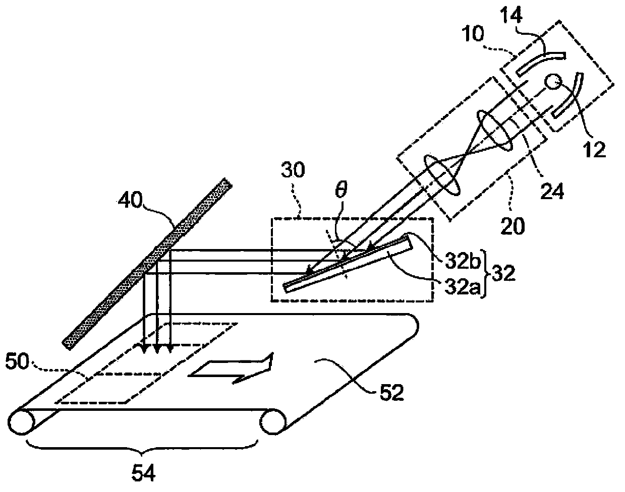
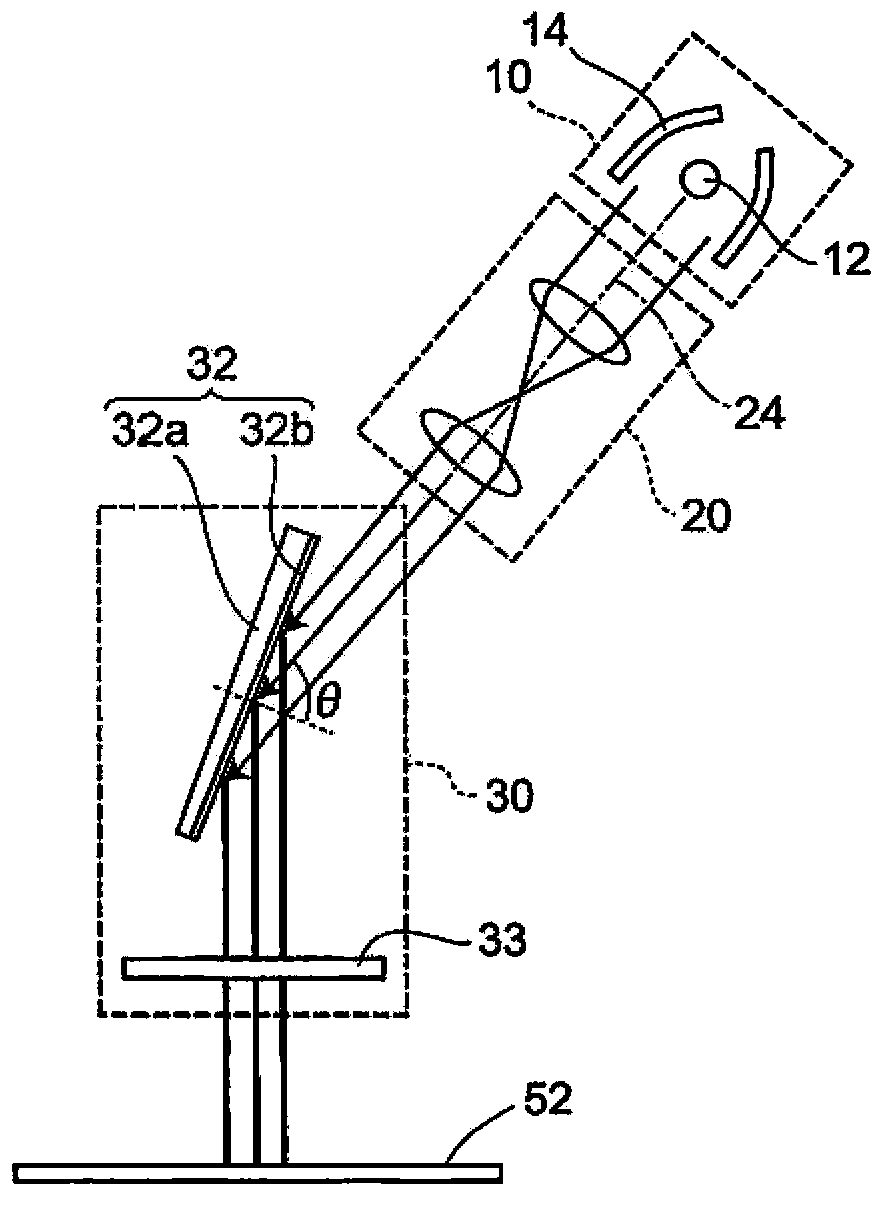
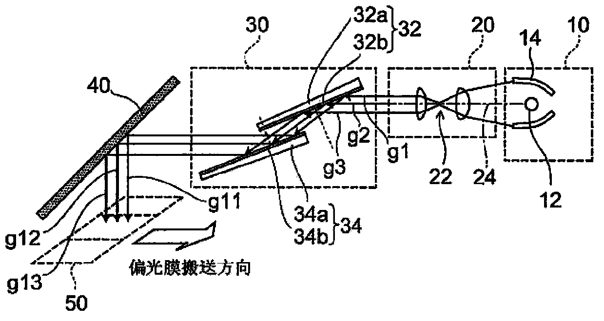
[0074] figure 1 It is a configuration diagram of the polarized light irradiation device according to the first embodiment of the present invention.

[0075] The polarized light irradiation device includes a light source unit 10 , a parallel light forming unit 20 and a polarized light forming unit 30 . The light source unit 10 includes an ultraviolet lamp 12, a condenser lens 14, and the like. The polarized light forming unit 30 includes a plate-type polarizing beam splitter 32 , splits the ultraviolet light emitted from the parallel light forming unit 20 into a p-polarized light component and an s-polarized light component, and emits the s-polarized light component as an irradiation beam. In addition, in the specification, "ultraviolet light" means light having a wavelength of 390 nm or less, and includes deep ultraviolet light.

[0076] The parallel light forming part 2...


PUM

PropertyMeasurementUnit
thicknessaaaaaaaaaa

Abstract

The invention provides a polarized light irradiating device capable of achieving high polarized light extinction ratio, uniform polarized light orientation, and large irradiating area. The polarized light irradiating device comprises a light source portion emitting ultraviolet light, a parallel light forming portion paralleling the ultraviolet light, and a polarized light forming portion. The polarized light forming portion comprises a plate polarizing beam splitter of a dielectric substance multilayer film disposed on a first face of a transparent board. In order to reflect s polarized light ingredient and transmit p polarized light ingredient in the ultraviolet light incident to the surface of the dielectric substance multilayer film in an inclined manner from the parallel light forming portion, the split s polarized light ingredient is emitted out as an irradiating beam.

Description

technical field [0001] Embodiments of the present invention relate to a polarized light irradiation device. Background technique [0002] Alignment films used in liquid crystal panels can be photo-aligned by irradiating linearly polarized light at an ultraviolet wavelength to the surface of a film such as polyimide resin. [0003] With the increase in the definition and size of liquid crystal panels, a high polarization extinction ratio, uniform polarization orientation, and large area of ​​the irradiation area are required for polarized light irradiation devices for photoalignment films. [0004] For example, in order to obtain transmitted light having a polarization extinction ratio of 100:1 or more using a polarizer including a transparent plate with a refractive index of 1.6, the number of laminated transparent plates must be 200 or more, resulting in a large device. [0005] Furthermore, in order to obtain linearly polarized light along the longitudinal direction of th...

Claims


Application Information

Patent Timeline
Patent Type & Authority Applications(China)
IPC IPC(8): G02F1/1337G02B27/28
Inventor 前田祥平野村博
Owner TOSHIBA LIGHTING & TECH CORP
Why Eureka
Try Eureka