
Method for optimizing and controlling little-cutting fluid processing technology in machining process

A technology of machining and optimization control, applied in the field of machining, can solve the problems of polluted environment, cutting fluid analysis, and inability to improve the current situation of cutting fluid consumption.

Inactive Publication Date: 2014-05-14
WUHAN UNIV OF SCI & TECH
View PDF1 Cites 10 Cited by
  • Summary
  • Abstract
  • Description
  • Claims
  • Application Information

AI Technical Summary

Problems solved by technology

[0002] Cutting fluid plays a very important role in the machining process and has brought about prominent negative effects, including greatly increasing manufacturing costs, seriously polluting the environment, directly endangering the health of operators, requiring cleaning and related costs, and other unfavorable factors. It is very necessary to develop and research the optimization control method of machining process with less cutting fluid in machining process
However, in the prior art, there is no corresponding method and tool to conduct an overall analysis of the use of cutting fluid in the machining process, and it is impossible to provide support for the process planning and process improvement of the machining process, and it is impossible to improve the cutting fluid. In this context, it is very important to reduce the amount of cutting fluid by combining the amount of cutting fluid with the optimization of process parameters and considering the manufacturing cost in the machining process, but the existing technology rarely involves The optimal control method of processing technology targeting the cutting fluid consumption (such as cutting fluid flow rate) in the processing process

Method used


Image

  • Method for optimizing and controlling little-cutting fluid processing technology in machining process
  • Method for optimizing and controlling little-cutting fluid processing technology in machining process
  • Method for optimizing and controlling little-cutting fluid processing technology in machining process

Examples


Embodiment Construction

[0065] In order to make the object, technical solution and advantages of the present invention more clear, the present invention will be further described in detail below in conjunction with the examples. It should be understood that the specific embodiments described here are only used to explain the present invention, not to limit the present invention.

[0066] The cutting fluid flow monitoring device is installed, and the cutting fluid after atomization and cooling is used to perform cutting processing on the workpiece.

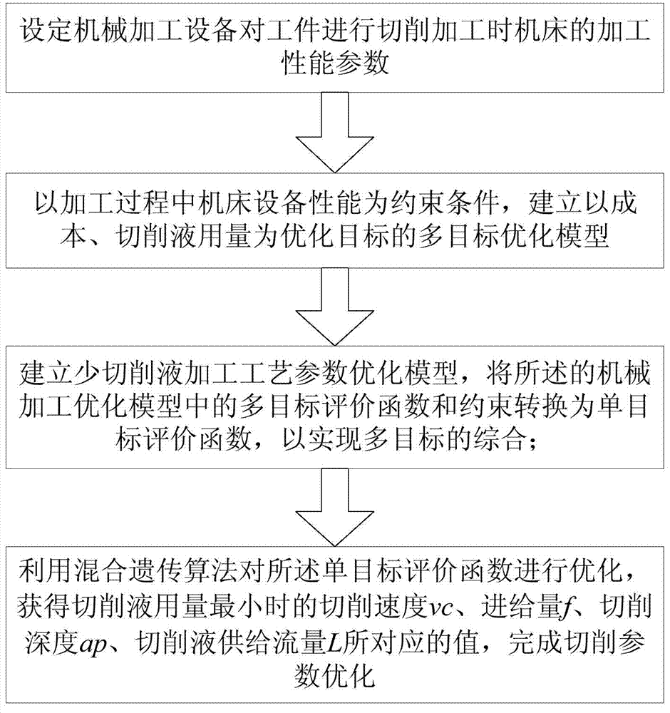
[0067] Such as figure 1 As shown, a machining process optimization control method with less cutting fluid in the machining process includes the following steps:

[0068] 1) When the machining equipment is used to cut the workpiece, the cutting speed of the tool is v c , feed rate is f, cutting depth a p , cutting fluid supply flow L;

[0069] 2) Establish a cutting parameter optimization model according to the cutting process.

[0070] According to t...


PUM


Abstract

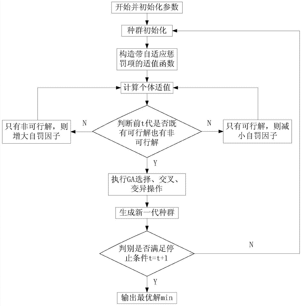
The invention provides a method for optimizing and controlling the little-cutting fluid processing technology in the machining process. The method comprises the following steps that the machining performance parameters of a machine tool are set when a machining device cuts a workpiece, a multi-objective optimization model with the machine tool performance in the machining process as the constraint condition and with the cost and the cutting fluid amount as optimization objectives is established, a little-cutting fluid processing technology parameter optimization model is established through the multi-objective optimization model and constraint, a multi-objective evaluation function and constraint are converted into a single-objective evaluation function, the single-objective evaluation function is optimized through the mixed genetic algorithm to obtain the cutting parameter value when the amount of the cutting fluid is minimum, and the cutting parameter optimization is finished. The amount of the cutting fluid in the machining process is more accurate through the method, the manufacturing cost is reduced, and support is provided for little-cutting fluid processing technology planning and technology improving in the machining process.

Description

technical field [0001] The invention relates to the field of mechanical cutting, in particular to a method for optimizing and controlling a machining process with less cutting fluid in the machining process. Background technique [0002] Cutting fluid plays a very important role in the machining process and has brought about prominent negative effects, including greatly increasing manufacturing costs, seriously polluting the environment, directly endangering the health of operators, requiring cleaning and related costs, and other unfavorable factors. It is very necessary to develop and research the optimization control method of machining process with less cutting fluid in machining process. However, in the prior art, there is no corresponding method and tool to conduct an overall analysis of the use of cutting fluid in the machining process, and it is impossible to provide support for the process planning and process improvement of the machining process, and it is impossibl...

Claims


Application Information

Patent Timeline
IPC IPC(8): G06F17/50
Inventor 江志刚周帆张华肖明鄢威周敏冯朝辉马峰李弼心
Owner WUHAN UNIV OF SCI & TECH
Learn More