Landing door for elevator
A technology for landing doors and elevators, applied to elevators, transportation, and packaging in buildings, which can solve problems such as difficulty in using panels and achieve the effect of easy manufacturing
- Summary
- Abstract
- Description
- Claims
- Application Information
AI Technical Summary
Problems solved by technology
Method used
Image

Examples
Embodiment approach 1
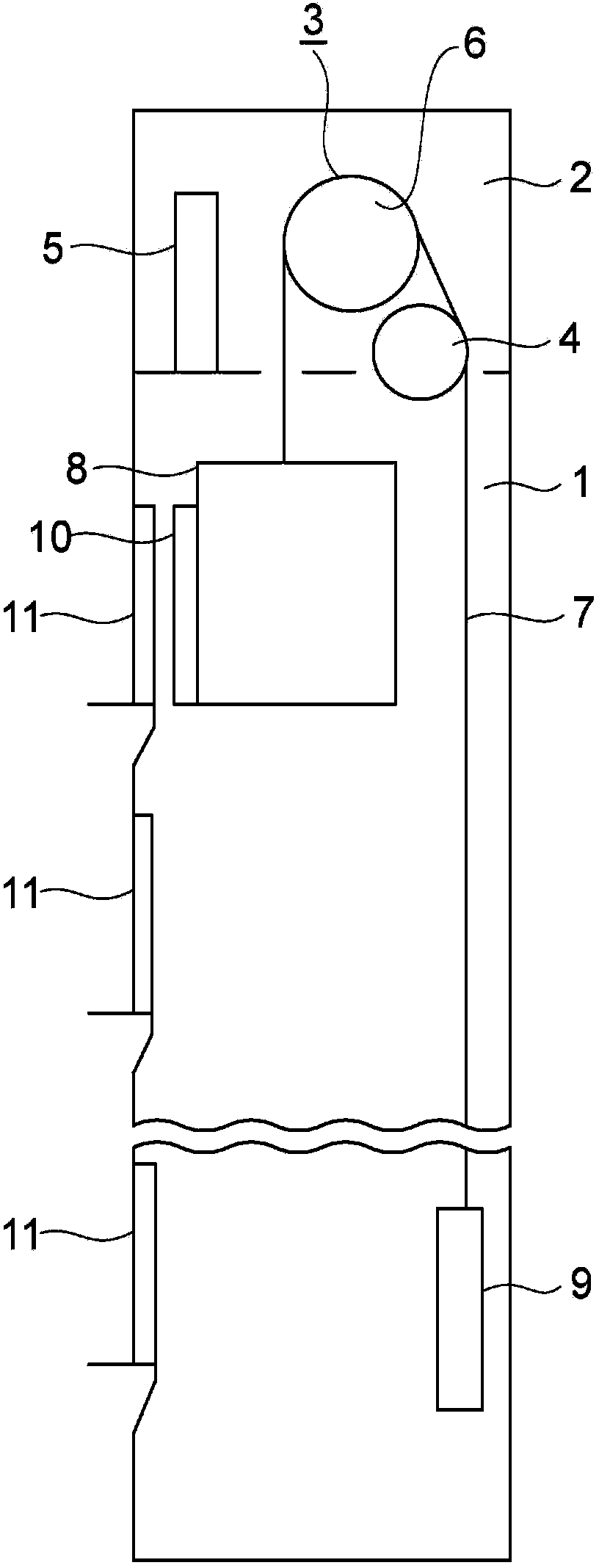
[0029] figure 1 It is a schematic block diagram which shows the elevator of Embodiment 1 of this invention. In the figure, a machine room 2 is provided in the upper part of the hoistway 1 . The machine room 2 is provided with a traction machine (driving device) 3 , a reverse sheave 4 and an operation control device (control panel) 5 . The hoisting machine 3 includes a driving sheave 6 , a hoisting machine motor that rotates the driving sheave 6 , and a hoisting machine brake (electromagnetic brake) that brakes the rotation of the driving sheave 6 .
[0030] The suspension unit 7 is wound around the drive sheave 6 and the return sheave 4 . The suspension unit 7 uses multiple ropes or multiple straps. The first end portion of the suspension unit 7 is connected to the car 8 . The second end of the suspension unit 7 is connected to the counterweight 9 .
[0031] The car 8 and the counterweight 9 are suspended in the hoistway 1 by the suspension unit 7 , and are moved up and d...
Embodiment approach 2
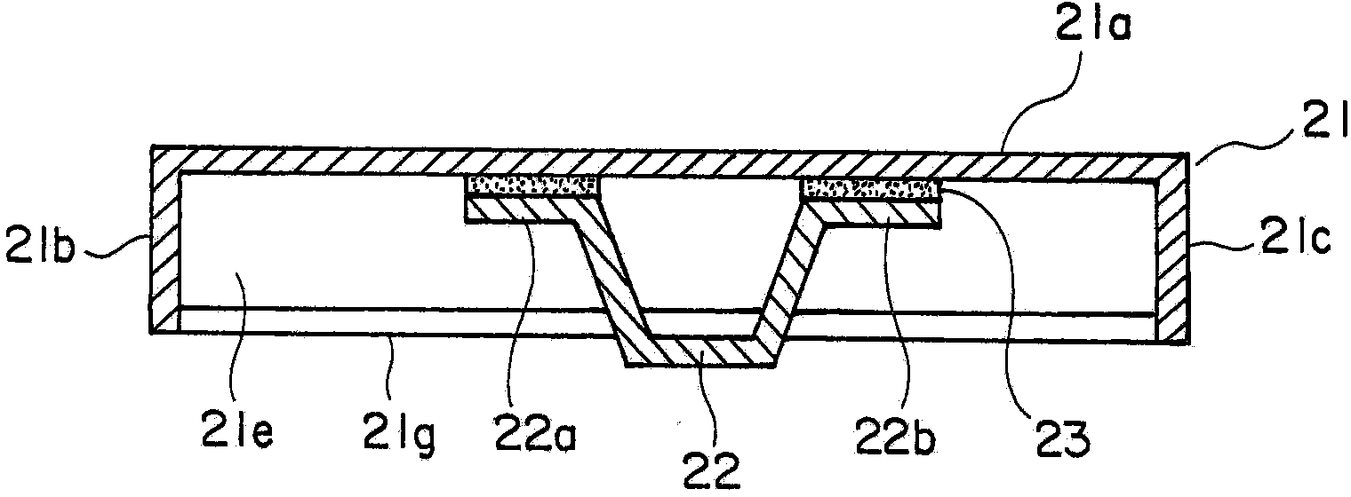
[0047] Figure 4 It is a cross-sectional view of a hall door according to Embodiment 2 of the present invention. In the figure, the primer layer 25 is interposed between the flat plate portion 21 a of the surface plate 21 and the adhesive tape 23 . The other structures are the same as those of the first embodiment.
[0048]A primer layer 25 is formed by thinly applying a primer to the adhesive portion on the back surface of the flat plate portion 21a, and then the reinforcing member 22 is adhered with an adhesive tape 23 made of an organic adhesive containing a flame retardant. Manufacture of such landing doors.
[0049] Primers are used to increase the bond strength between the metal and the adhesive. When a phosphoric acid oxide such as an aqueous organic phosphoric acid compound is used as the primer, the adhesive strength with metal based on the acrylic adhesive can be increased.
[0050] That is, by providing the primer layer 25 , the adhesive strength between the sur...
Embodiment approach 3
[0052] under, Figure 5 It is a cross-sectional view of a hall door according to Embodiment 3 of the present invention. In the figure, a thermoplastic resin layer 26 is provided between the adhesively fixed portions 22a and 22b of the reinforcing member 22 and the adhesive tape 23 . The other structures are the same as those of the first embodiment.
[0053] The thermoplastic resin layer 26 is formed by applying a thermoplastic resin thinly to a part of the bonding and fixing portions 22a and 22b, and cooling and solidifying, and then the reinforcing member 22 is bonded to the surface plate 21 with the adhesive tape 23, thereby producing this Terminal door.
[0054] If the temperature of the adhesive tape 23 rises during a fire, the thermoplastic resin will soften and melt in a short time. Therefore, in the event of a fire, the reinforcing member 22 is peeled off from the adhesive tape 23 in a state where the adhesive tape 23 is attached to the back side of the front panel ...
PUM
 Abstract
Description
Claims
Application Information
 - R&D Engineer
- R&D Manager
- IP Professional
- Industry Leading Data Capabilities
- Powerful AI technology
- Patent DNA Extraction
Browse by: Latest US Patents, China's latest patents, Technical Efficacy Thesaurus, Application Domain, Technology Topic.
© 2024 PatSnap. All rights reserved.Legal|Privacy policy|Modern Slavery Act Transparency Statement|Sitemap