Mire machine self-rescuing device

A technology of machinery and quagmire, which is applied to agricultural machinery, agricultural machinery and implements, and sowing. It can solve the problems of consuming a lot of manpower and material resources, and easily causing safety accidents. It achieves low manufacturing cost, convenient use, and simple structure. Effect

Inactive Publication Date: 2014-05-21
湘乡市高峰五金机械制造有限公司
View PDF7 Cites 8 Cited by
  • Summary
  • Abstract
  • Description
  • Claims
  • Application Information

AI Technical Summary

Problems solved by technology

[0002] At present, when agricultural machinery such as paddy field plowing, sowing, cutting seedlings, and harvesting encounter deep-footed mud fields and local small puddles in paddy fields, they usually get stuck in the quagmire due to carelessness or ignorance. People help push and pull or use other vehicles to get out of the predicament. Although agricultural machinery manufacturers have made many improvements to solve the problem, such problems still exist. This not only consumes a lot of manpower and material resources, but also delays farming. It is easy to cause safety accidents

Method used


Image

  • Mire machine self-rescuing device
  • Mire machine self-rescuing device

Examples


Embodiment 1

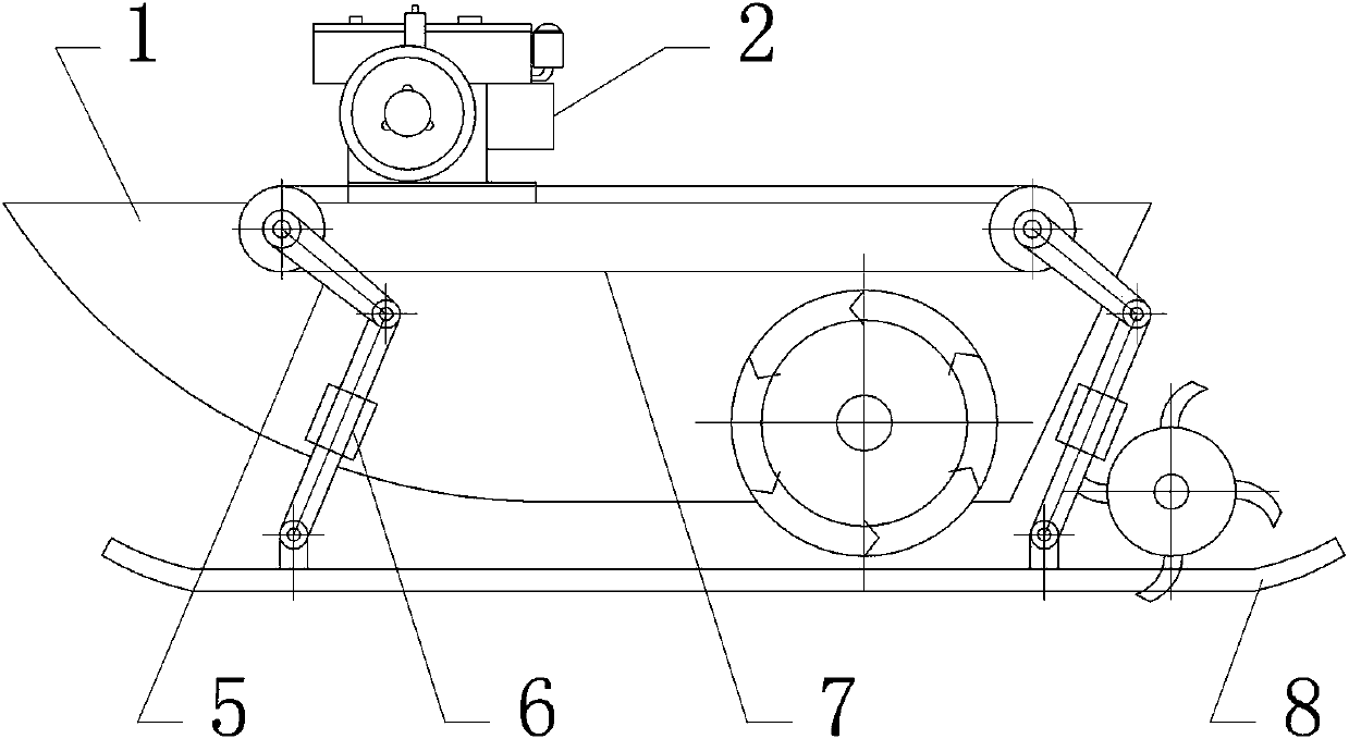
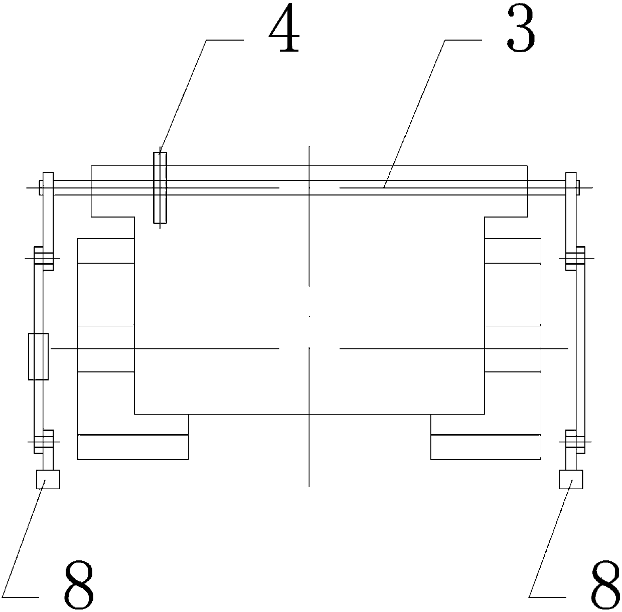
[0014] Embodiment 1, the present invention includes a main machine 1 and an engine 2, which is characterized in that: the main machine 1 is provided with an engine 2 to provide power for the entire device, the main machine 1 is equipped with a linkage axle 3, and the linkage axle 3 is provided with a linkage A linkage chain 7 is arranged between the sprocket 4 and the linkage sprocket 4. When the power output wheel chain is connected to the linkage wheel, the linkage axle 3 rotates synchronously through the linkage chain 7 between the linkage sprocket 4, so that all linkage axles 3 can be synchronized Movement, both sides of the linkage axle 3 are equipped with self-rescue lifting rocker arms 5, the linkage axle 3 drives the rocker crank mechanism to generate rotational motion, the other end of the self-rescue lifting rocker arm 5 is connected to the self-rescue lifting rocker arm 6 5 drives the self-rescue adjustable lifting connecting rod 6, the self-rescue adjustable lifting...

Embodiment 2

[0015] Embodiment 2, the present invention is provided with two or more interlocking axles 3, and the number of interlocking axles 3 can be appropriately adjusted according to actual factors such as the length of the main machine 1. Front side and rear side, if want other special requirements, also can be arranged on the middle part or other required positions, linkage axle 3 two ends protrude main body machine 1 both sides, reserve space for the installation of other parts such as self-rescue lifting rocker arm 5. refer to Figure 1 to Figure 2 , all the other are with embodiment 1.

Embodiment 3

[0016] Embodiment 3, the skateboard 8 of the present invention is provided with protruding connecting parts corresponding to the number of linkage wheel shafts 3, and the protruding connecting parts are connected with the self-rescue adjustable lifting connecting rod 6. The skateboard 8 adopts an oval airbag-type movable skateboard, When the main machine 1 is in normal operation, the slide boards can be stored at the freeboard positions on both sides of the ship. refer to Figure 1 to Figure 2 , and the rest are the same as the above-mentioned embodiment.


PUM


Abstract

The invention discloses a mire machine self-rescuing device and belongs to an agricultural machinery device. The mire machine self-rescuing device mainly solves the technical problems that an existing agricultural machinery self-rescuing device is complicated in structure, not convenient to use, poor in adaptability, high in manufacturing cost and the like. The mire machine self-rescuing device is characterized in that an engine (2) is arranged on a body machine (1) which is provided with a linkage axle (3) which is provided with linkage chain wheels (4), and a linkage chain (7) is arranged between the linkage chain wheels (4). The two sides of the linkage axle (3) are provided with self-rescuing lifting rocker arms (5), and the other ends of the self-rescuing lifting rocker arms (5) are connected with a self-rescuing adjustable lifting connection rod (6) which is connected with a sliding board (8). The mire machine self-rescuing device is mainly used for self-rescuing after the machine mires down in mud.

Description

technical field [0001] The invention relates to a mechanical device, in particular to a mechanical self-rescue device for quagmire. Background technique [0002] At present, when agricultural machinery such as paddy field plowing, sowing, cutting seedlings, and harvesting encounter deep-footed mud fields and local small puddles in paddy fields, they usually get stuck in the quagmire due to carelessness or ignorance. People help push and pull or use other vehicles to get out of the predicament. Although agricultural machinery manufacturers have made many improvements to solve the problem, such problems still exist. This not only consumes a lot of manpower and material resources, but also delays farming. It is easy to cause safety accidents. Contents of the invention [0003] The purpose of the present invention is to provide a quagmire mechanical self-rescue device for paddy field operations with simple structure, convenient use, wide adaptability and low manufacturing cos...

Claims


Application Information

Patent Timeline
Patent Type & Authority Applications(China)
IPC IPC(8): A01D75/00A01C7/00A01B71/00
Inventor 高峰高名和
Owner 湘乡市高峰五金机械制造有限公司
Why Eureka
Try Eureka