Vertical circular spraying chamber applied to powder spray-coating line

A technology of spraying line and spray booth, which is applied to the device for coating liquid on the surface, the cleaning method using gas flow, coating, etc., which can solve the problem of not meeting the production needs of enterprises, increasing production costs, and wearing parts Many problems, to achieve the effect of saving color changing time, reducing energy consumption, and reducing production costs

Active Publication Date: 2014-05-21
ZHONGSHAN JUNHE ELECTRO MECHANICAL APP
View PDF7 Cites 5 Cited by
  • Summary
  • Abstract
  • Description
  • Claims
  • Application Information

AI Technical Summary

Problems solved by technology

[0003] refer to figure 2 , U-shaped vertical powder spray booth, also use transparent plastic film to make three baffles 2 1'', three baffles 2 1'' enclose to form a U-shaped opening groove, two adjacent baffles 2 1 There is an air draft slit between the '', the air exhaust pipe 2 10'' is connected to the air draft slit, and a suspension chain 2'' extending along the opening shape of the U-shaped opening groove is provided at the opening end of the U-shaped opening groove. The chain 2'' transports the workpieces to the opening end of the U-shaped open slot in turn for powder coating, and then sends them away. When powder coating the workpieces, a lot of dust will be produced in the air, so it is necessary to start the exhaust fan and pass The air duct two 10'' takes away t

Method used


Image

  • Vertical circular spraying chamber applied to powder spray-coating line
  • Vertical circular spraying chamber applied to powder spray-coating line
  • Vertical circular spraying chamber applied to powder spray-coating line

Examples


Embodiment Construction

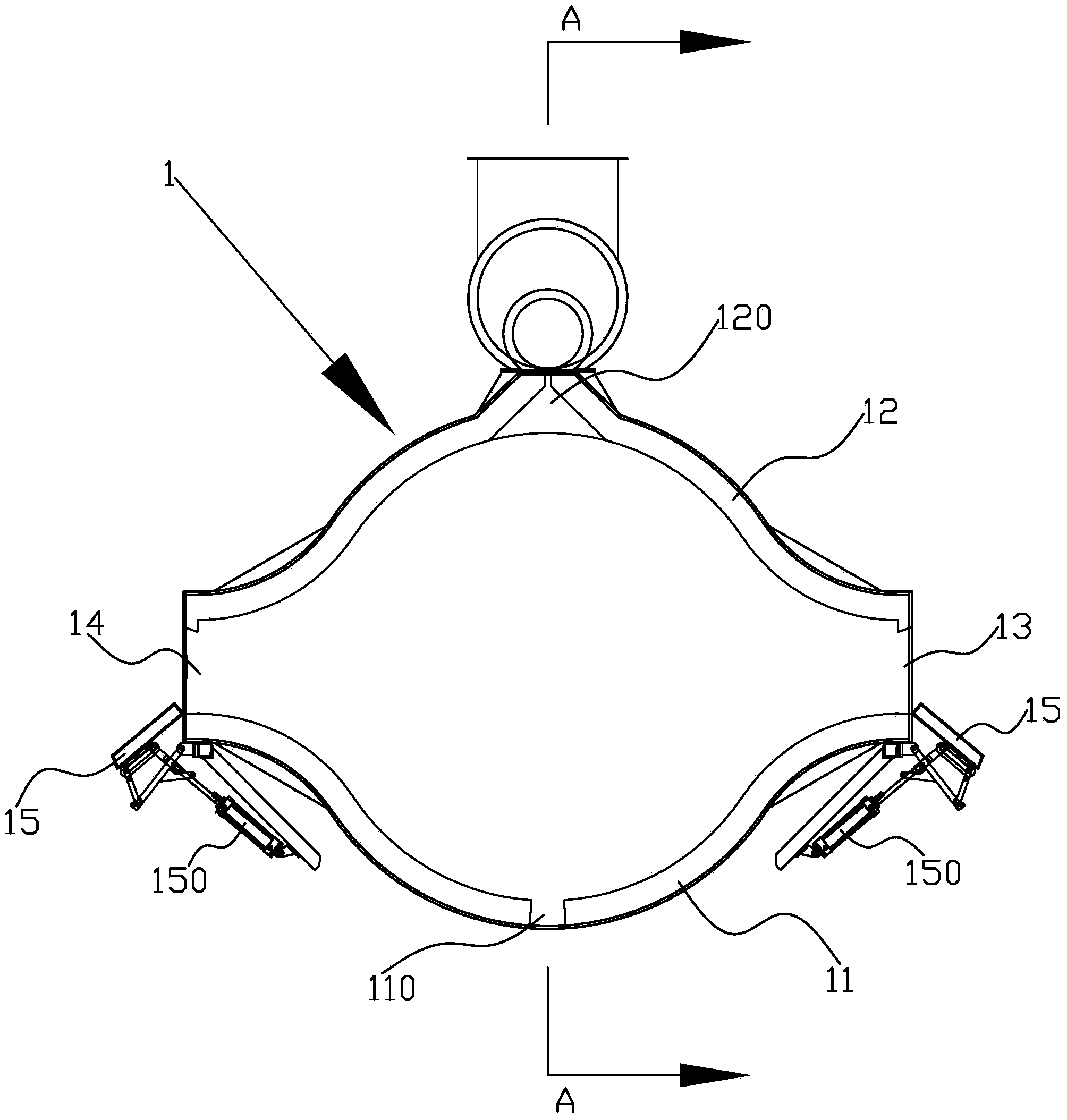
[0025] Reference image 3 To Figure 8, a vertical circular spray booth applied to a powder spraying line includes a vertical spray booth main body 1, which is mainly composed of a front side plate 11 and a rear side plate 12 located on the front and rear sides. The front side plate 11 and the rear side plate 12 are preferably made of plastic plates. Therefore, the front side plate 11 and the rear side plate 12 are not conductive, which reduces the production cost and facilitates spraying powder. To make the front side panel 11 and the rear side panel 12 have sufficient strength, the front side panel 11 and the rear side panel 12 are made of PP panels with a sandwich structure. Of course, the front side panel 11 and the rear side panel 12 are made of single-layer plastic panels or other Insulating materials are also possible; the middle parts of the front and rear side plates 11, 12 are arched outward to form an arc shape, so that the appearance of the spray booth body 1 looks li...


PUM


Abstract

The invention discloses a vertical circular spraying chamber applied to a powder spray-coating line. The vertical circular spraying chamber comprises a vertical spraying chamber main body, wherein the spraying chamber main body is formed mainly by defining a front side plate and a rear side plate which are positioned on the front and rear sides respectively; the middle parts of the front and rear side plates are outwards arched to form circular arcs; a feed opening and a discharge opening are formed in the left and right sides of the spraying chamber main body respectively, and are used for the feeding and discharging of a workpiece; an air draft opening connected with an external air draft pipeline is formed in the outwards-arched position of the middle part of the rear side plate. According to the vertical circular spraying chamber, the front and rear side plates define a relatively enclosed space, and the middle parts of the front and rear side plates are outwards arched to form the circular arcs, so that the space in the spraying chamber is enough for the powder spray-coating of the workpiece, the feed opening and the discharge opening in the left and right sides of the spraying chamber are small, the opening area of the spraying chamber is reduced, and the requirements of the spraying chamber on air draft can be met by a relatively low-power draft fan.

Description

Technical field [0001] The invention relates to the field of powder spraying, in particular to a spray booth for powder spraying lines. Background technique [0002] At present, there are two main types of vertical powder spraying line spray booths that exist and are used in the market, namely V-shaped vertical powder spraying booth and U-shaped vertical powder spraying booth. figure 1 , The structure of the V-shaped vertical powder spray booth is relatively simple. The transparent plastic film is used to make two identical splints-1'. The two splints-1'are enclosed to form a V-shaped opening slot, and one is provided at the rear of the opening slot. Suction slot, the suction slot is connected with a suction pipe 10', the open end of the opening slot is provided with a suspension chain 2'extending along the opening shape, and the suspension chain 2'transports the workpieces to the opening end of the opening slot in turn Do powder spraying, and then send it away. When powder spray...

Claims


Application Information

Patent Timeline
IPC IPC(8): B05C19/04B05C19/06B05B15/12B05B14/41B05B14/44B05B14/48B05B16/40
CPCB05B14/41B05B14/44B05B14/48B05B16/405B08B5/02B08B15/02Y02P70/10
Inventor 李朝辉谢志超
Owner ZHONGSHAN JUNHE ELECTRO MECHANICAL APP
Why Eureka
Try Eureka