Numerical control gantry type multi-head linear cutting machine tool

A technology of cutting machine tools and multi-head wires, which is applied in the direction of electric processing equipment, electrode manufacturing, metal processing equipment, etc., can solve the problems of large occupied area and cost waste, reduce occupied area, improve production efficiency, improve processing accuracy and The effect of surface finish

Inactive Publication Date: 2014-05-21
浙江柯罗特精密机械设备有限公司
View PDF8 Cites 11 Cited by
  • Summary
  • Abstract
  • Description
  • Claims
  • Application Information

AI Technical Summary

Problems solved by technology

For large molds, a larger transmission structure is adopted, which occupies a larger area and wastes more cost

Method used


Image

  • Numerical control gantry type multi-head linear cutting machine tool
  • Numerical control gantry type multi-head linear cutting machine tool

Examples


Embodiment Construction

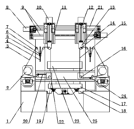
[0017] Below in conjunction with accompanying drawing and embodiment the present invention is described further non-limitatively:

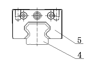
[0018] figure 1 and figure 2Among them, the CNC gantry type multi-head wire cutting machine tool includes a bed base 1, a workbench 17 is arranged on the bed base 1, and a guide rail assembly 18 is provided between the bed base 1 and the workbench 17, and the workbench 17 can be placed on the bed base 1 to move, the workbench 17 is provided with a support member 19 supporting the workpiece 23, and a crossbeam 21 and a Y lower arm 25 are arranged above the workbench. The X-axis motor that the body 1 moves, a wire transport mechanism is provided between the workbench 17 and the crossbeam 21, and the wire transport mechanism includes a mutually symmetrical left silk transport mechanism and a right silk transport mechanism, and the left and right silk transport mechanisms are respectively provided with left, The left and right electrode wires 3 ...


PUM


Abstract

The invention relates to a numerical control gantry type multi-head linear cutting machine tool. An operation platform is arranged on a tool body base, a cross beam is arranged above the operation platform, a left wire conveying mechanism and a right wire conveying mechanism are arranged between the operation platform and the cross beam, and a left electrode wire and a right electrode wire form left electrode wire circulation and right electrode wire circulation respectively through guide wheels. Upper guide wheels and lower guide wheels are arranged at the upper portions and the lower portions of the wire cutting sections of the electrode wires. A left upper lead screw transmission mechanism, a right upper lead screw transmission mechanism, a left Z-axis seat and a right Z-axis seat are arranged on the cross beam. The upper lead screw transmission mechanisms comprise Y-axis upper motors and upper lead screws, Z-axis sliding seats are connected onto the Z-axis seats, and the upper guide wheels are arranged on the Z-axis sliding seats. The lower guide wheels are arranged on Y-axis lower dragging plates which are connected with lower lead screws, and the lower lead screws are connected with Y-axis lower motors capable of driving the Y-axis lower dragging plates to move in a left and right mode. By means of the two wire conveying mechanisms, rough machining and fine machining can be separated; by means of the electrode wires different in mass, loss of the electrode wires is reduced, machining accuracy is improved, production cost and labor intensity of workers are reduced, occupied area of the device is reduced, and production efficiency is increased.

Description

technical field [0001] The patent of the present invention relates to the technical field of a wire cutting machine tool, in particular to the structure of the wire cutting machine tool and the wire feeding mechanism. Background technique [0002] CNC wire cutting machine tools are usually composed of three major parts: mechanical, electrical and working fluid systems. The mechanical system is composed of machine bed, coordinate table, wire feeding mechanism, wire frame mechanism, taper mechanism, lubrication system and so on. The bed of the machine tool is usually a box-type structure, which provides an installation platform for various components, and is closely related to the accuracy of the machine tool. The coordinate table is usually composed of cross carriage, rolling guide rail, screw motion pair, gear transmission mechanism and other parts. It is mainly the relative movement with the electrode wire to complete the processing of the workpiece. The wire feeding mec...

Claims


Application Information

Patent Timeline
IPC IPC(8): B23H7/02B23H7/26B23H7/10
Inventor 戴运山毛万林毛亚楠毛智勇赵百元
Owner 浙江柯罗特精密机械设备有限公司
Why Eureka
Try Eureka