Die cutting machine detection method

A detection method and die-cutting machine technology, which is applied in metal processing and other fields, can solve problems such as delays in die-cutting work progress, damage to die-cutting machines, and delays in die-cutting efficiency, so as to improve work efficiency and avoid misjudgment

Inactive Publication Date: 2016-01-13
LINK LABEL MACHINERY
View PDF5 Cites 0 Cited by
  • Summary
  • Abstract
  • Description
  • Claims
  • Application Information

AI Technical Summary

Problems solved by technology

Unfortunately, the wrong choice of die cutting before die cutting is a frequent but unavoidable human error. If the wrong choice of die cutting is small, it will delay the efficiency of the die-cutting pre-check work or delay the progress of the die-cutting work. The entire die-cutting machine may be damaged due to the use of the wrong die-cutting die, resulting in unnecessary equipment warranty costs

Method used


Image

  • Die cutting machine detection method
  • Die cutting machine detection method
  • Die cutting machine detection method

Examples


Embodiment Construction

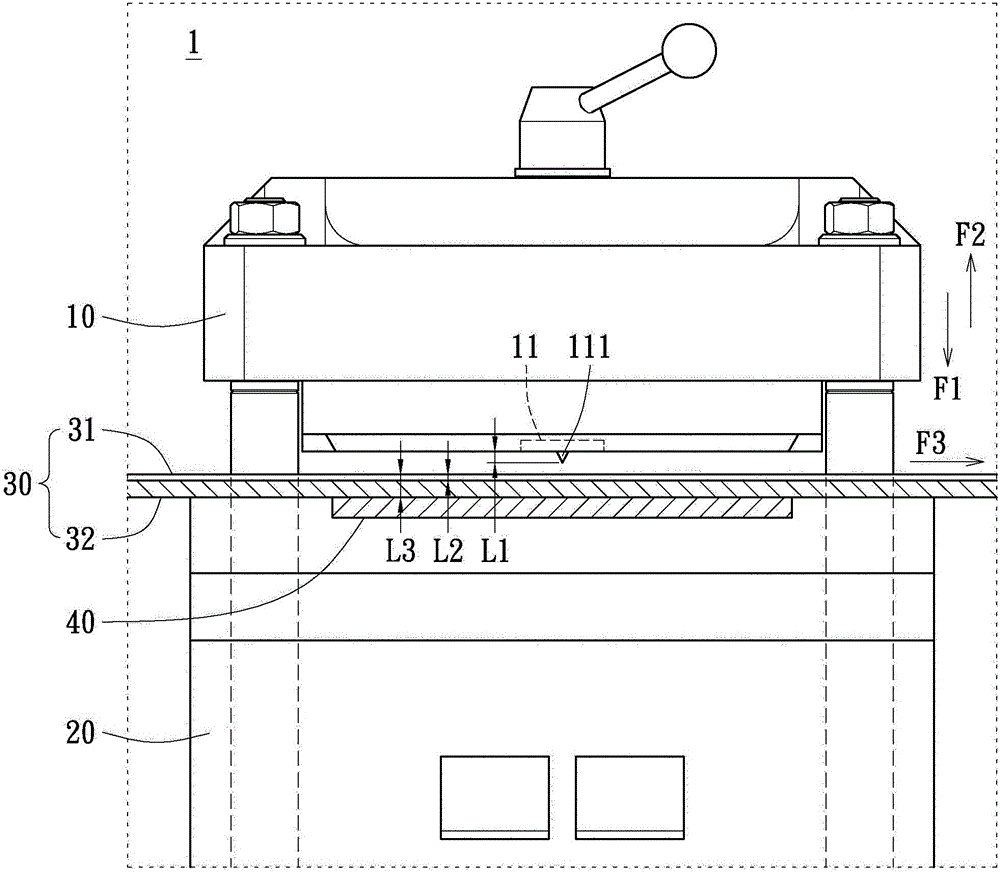
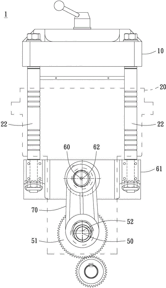
[0045] see figure 1 and Figure 5 As shown, the present invention provides a method for detecting a die-cutting machine. The die-cutting machine 1 at least includes a knife seat 10 and a processing seat 20 corresponding to the knife seat 10. The knife seat 10 is equipped with a knife die 111, and the knife die 111 Located on a die holder 11 of the cutter holder 10, a base paper 30 and a supplementary material 40 are laid on the processing base 20. The base paper 30 includes a side material 31 and a release paper 32. When the die-cutting machine is tested, a knife is installed The knife seat 10 of the mold 111 can move up and down along the cutting direction F1 or the return direction F2, and if the knife seat 10 moves up and down during the die-cutting process, the bottom paper 30 on the processing seat 20 will be fed along the paper feeding direction. Direction F3 continues to convey.

[0046] Die-cutting machine detection method of the present invention comprises the follo...


PUM


Abstract

The invention discloses a film cutting machine detecting method. A film cutting machine at least comprises a tool apron and a machining base corresponding to the tool apron. A tool film is installed on the tool apron, and the machining base is paved with a piece of bottom paper and a supplement material. The bottom paper comprises a plane material and a piece of release paper. The film cutting machine detecting method comprises the following steps that a film cutting parameter comprising a tool film height numerical value corresponding to the tool film, a bottom paper thickness numerical value corresponding to the bottom paper and a supplement material thickness numerical value corresponding to the supplement material is input, the film cutting parameter is compared with a film cutting parameter database to form a corresponding first tool film contact stroke, the tool film is made to move towards the bottom paper to explore a tool, a second tool film contact stroke is recorded when the tool film makes contact with the bottom paper, the first tool film contact stroke and the second tool film contact stroke are compared, and a primary tool film detecting result is generated. The accuracy of the tool film is judged according to the primary tool film detecting result.

Description

technical field [0001] The invention relates to a detection method of a die-cutting machine, in particular to a detection method of a die-cutting machine for detecting whether the corresponding relationship between the cutting die of the die-cutting machine and objects to be cut such as backing paper and supplementary materials is correct. Background technique [0002] Generally speaking, after the self-adhesive paper is printed on the surface material and the surface material is glued back to the release paper (substrate), the processor needs to further cut the surface material to leave a tearable cut on the surface material. Traces, this is die-cutting, so that future users can freely tear off the surface material with printed patterns and characters from the release paper. [0003] Die-cutting is an extremely fine cutting process, so the model and thickness of the die (or tool) must be extremely precise and correspond to the thickness of the object to be cut in order to c...

Claims


Application Information

Patent Timeline
Patent Type & Authority Patents(China)
IPC IPC(8): B26D5/00
Inventor 刘兴人刘政良彭骏逸
Owner LINK LABEL MACHINERY
Why Eureka
Try Eureka