Method and system used for heating wafers on static chuck, and CVD equipment

An electrostatic chuck and wafer technology, which is applied in gaseous chemical plating, metal material coating process, coating, etc., can solve the problem of strong temperature disturbance, large temperature time constant and time lag, and difficult PID controller parameter tuning. and other problems to achieve the effect of ensuring temperature and suppressing temperature disturbance

Inactive Publication Date: 2014-05-21
BEIJING NAURA MICROELECTRONICS EQUIP CO LTD
View PDF4 Cites 4 Cited by
  • Summary
  • Abstract
  • Description
  • Claims
  • Application Information

AI Technical Summary

Problems solved by technology

[0004] To sum up, the disadvantage of the prior art is that the various parts of the heater are not isolated, but interrelated, and the heater is covered with a layer of uniform heat medium, which has good thermal conductivity, so the temperature of each part of the heater It is a coupling relationship, the temperature disturbance is strong, and the time constant and time lag of temperature are large
Therefore, it is difficult to achieve the ideal regulation and control effect by using a single-loop independent temperature PID controller
Especially when the set temperature of each zone is inconsistent, it is difficult to set the parameters of the PID controller

Method used


Image

  • Method and system used for heating wafers on static chuck, and CVD equipment
  • Method and system used for heating wafers on static chuck, and CVD equipment
  • Method and system used for heating wafers on static chuck, and CVD equipment

Examples


Embodiment Construction

[0064] Embodiments of the present invention are described in detail below, examples of which are shown in the drawings, wherein the same or similar reference numerals designate the same or similar elements or elements having the same or similar functions throughout. The embodiments described below by referring to the figures are exemplary only for explaining the present invention and should not be construed as limiting the present invention.

[0065] The following disclosure provides many different embodiments or examples for implementing different structures of the present invention. To simplify the disclosure of the present invention, components and arrangements of specific examples are described below. Of course, they are only examples and are not intended to limit the invention. Furthermore, the present invention may repeat reference numerals and / or letters in different instances. This repetition is for the purpose of simplicity and clarity and does not in itself indicat...


PUM


Abstract

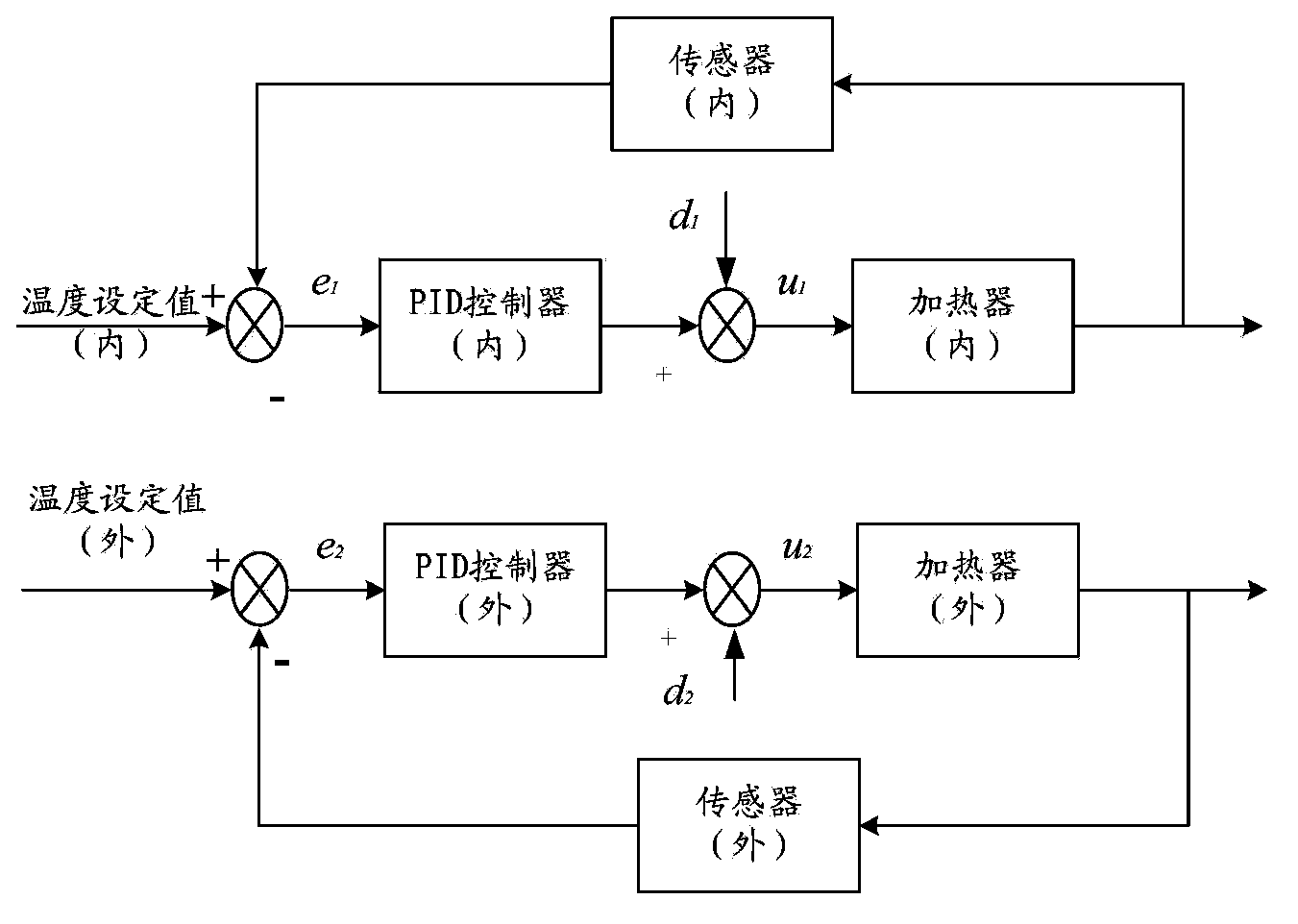
The invention discloses a method used for heating wafers on a static chuck. The static chuck comprises a first heating zone corresponding to a first heater, and a second heating zone corresponding to a second heater. The method comprises following steps: a first target temperature of the first heating zone and a second target temperature of the second heating zone are obtained; a first detecting temperature of the first heating zone and a second detecting temperature of the second heating zone are detected; a first error signal is calculated according to the first target temperature and the first detecting temperature, and a second error signal is calculated according to the second target temperature and the second detecting temperature; a first correcting signal and a second correcting signal are calculated according to the first error single and the second error single respectively; and control signal of the first heater and control signal of the second heater are obtained according to the first correcting signal and the second correcting signal respectively. The method is capable of adjusting temperature changing speed of different heating zones of the heaters effectively, and inhibiting temperature disturbance effectively. The invention also provides a system and CVD equipment used for heating the wafers on the static chuck.

Description

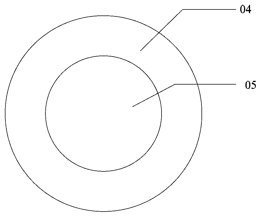
technical field [0001] The present invention relates to the field of semiconductor technology, in particular to a method and system for heating a wafer on an electrostatic chuck and a CVD (Chemical-Vapor-Deposition, chemical vapor deposition) system with the system for heating a wafer on an electrostatic chuck )equipment. Background technique [0002] In the etching process, uneven wafer temperature will cause uneven etching results, so that some areas of the wafer after etching have high RA (Roughness Average, surface flatness), while other areas have poor RA. Due to the higher deposition coefficient of polymers at low temperatures, temperatures lower than predetermined process parameters can cause excessive polymer deposition on the wafer, resulting in poor RA in the lower temperature regions of the wafer, resulting in poor etch results. The features have tapered sidewalls and these polymer deposits are difficult to remove from the wafer, so this etch effect should be min...

Claims


Application Information

Patent Timeline
IPC IPC(8): C23C16/46
Inventor 张敏宗令蓓
Owner BEIJING NAURA MICROELECTRONICS EQUIP CO LTD
Why Eureka
Try Eureka