

Device and method for inductive current sampling of bridge-free PFC circuit
A technology of inductor current and sampling device, which is applied in the field of electricity, can solve the problems of reduced reliability of power supply and small duty cycle of PFC circuit, etc., and achieve the effects of reducing difficulty and complexity, flexible control, and comprehensive sampling
- Summary
- Abstract
- Description
- Claims
- Application Information
AI Technical Summary
Problems solved by technology
Method used
Image

Examples
example 1
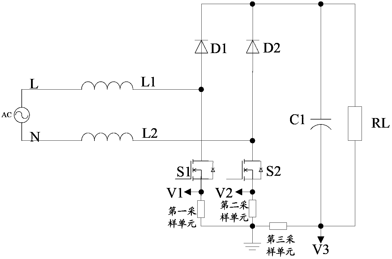
[0039] Example 1, the first sampling unit is the first sampling resistor Rs1, the second sampling unit is the second sampling resistor Rs2, and the third sampling unit is the third sampling resistor Rs3.
[0040] Figure 4 It is a structural schematic diagram of Example 1 of the embodiment of the present invention, such as Figure 4 As shown, the first end of the first inductance L1 of the bridgeless PFC circuit is connected to the first end of the AC power supply of the bridgeless PFC circuit, and the second end of the first inductance L1 is connected to the first boost diode D1 of the bridgeless PFC circuit connected to the anode of the bridgeless PFC circuit, and connected to the first end of the first switch S1 of the bridgeless PFC circuit; the second end of the first switch S1 is connected to the first end of the first sampling resistor Rs1, and sends out the inductance of the bridgeless PFC circuit The first sampling signal V1 of the current; the second terminal of the...
example 2
[0043] Example 2, the first sampling unit is the first current mutual induction device, the second sampling unit is the second current mutual induction device, and the third sampling unit is the third current mutual induction device;
[0044] Figure 5 It is a schematic diagram of Example 2 of the embodiment of the present invention, such as Figure 5 As shown, the first current mutual induction device includes: a first current transformer CT1, a fifth resistor R5, a fifth diode D5, and a fourth sampling resistor Rs4, the first end of the secondary side of the first current transformer CT1 is connected to the first The first end of the fifth resistor R5 is connected, the anode of the fifth diode D5 is connected to the first end of the fifth resistor R5, the cathode of the fifth diode D5 is connected to the first end of the fourth sampling resistor Rs4, and Sending the first sampling signal V1 of the inductor current of the bridgeless PFC circuit, the second end of the fifth r...
PUM
 Abstract
Description
Claims
Application Information