Lead-acid storage battery tubular plate powder filling device

A technology of lead-acid batteries and pole plates, which is applied in the direction of lead-acid battery electrodes, battery electrodes, and electrode manufacturing. It can solve the problems of low powder filling efficiency, inconvenient loading and unloading, and dust pollution, so as to reduce dust pollution and increase pole plates Quantity, the effect of improving production efficiency

Active Publication Date: 2014-05-21
ZHAOQING LEOCH BATTERY TECH
View PDF3 Cites 11 Cited by
  • Summary
  • Abstract
  • Description
  • Claims
  • Application Information

AI Technical Summary

Problems solved by technology

The powder filling device of the traditional lead-acid battery tube plate is as follows: figure 2 As shown, it includes a feed hopper 101, a pole plate assembly tool 103, a vibrating table 104, and a chassis 105. When using this device for powder filling, the operator needs to put the plate 102 into the powder filling device piece by piece before powder filling. After the end, it is necessary to take out the plates one by one, which makes loading and unloading very inconvenient; in order to protect the plates from being damaged during the powder filling process, a gap needs to be left between adjacent plates, so the number of tubular plates for each powder filling There are only about 7 pieces, and the powder filling efficiency is low; during the powder filling process, the bottom of the plate is easy to slide out of the slot due to vibration, and it needs to be manually returned to its position. For the convenience of operation, most operators open the powder filling machine door Working in a harsh environment, the operating environment is poor, and the dust pollution is serious

Method used


Image

  • Lead-acid storage battery tubular plate powder filling device
  • Lead-acid storage battery tubular plate powder filling device
  • Lead-acid storage battery tubular plate powder filling device

Examples


Embodiment Construction

[0023] The present application will be described in further detail below through specific embodiments in conjunction with the accompanying drawings.

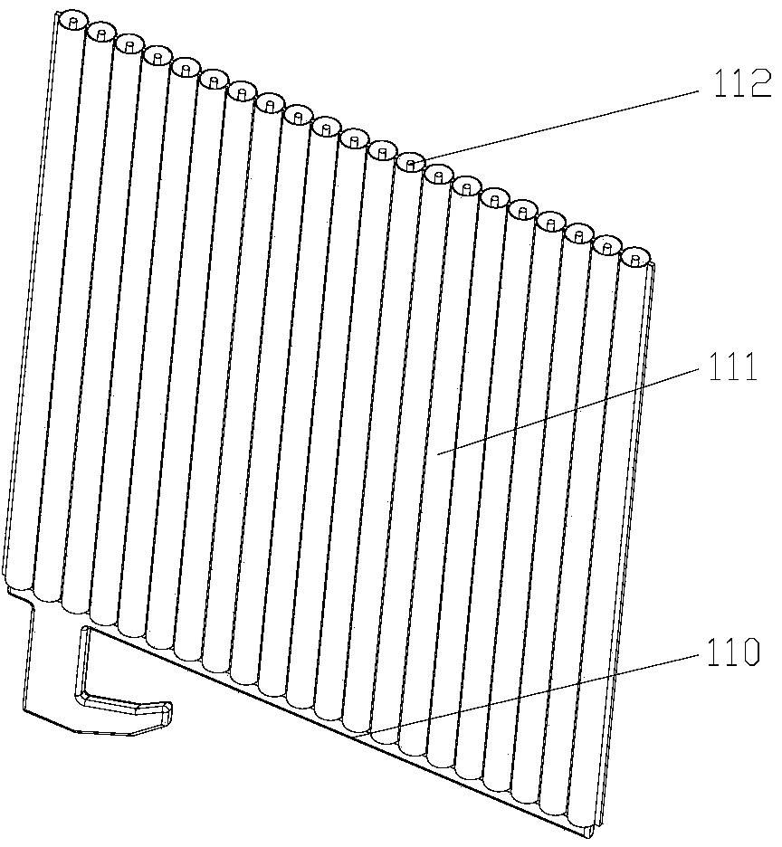
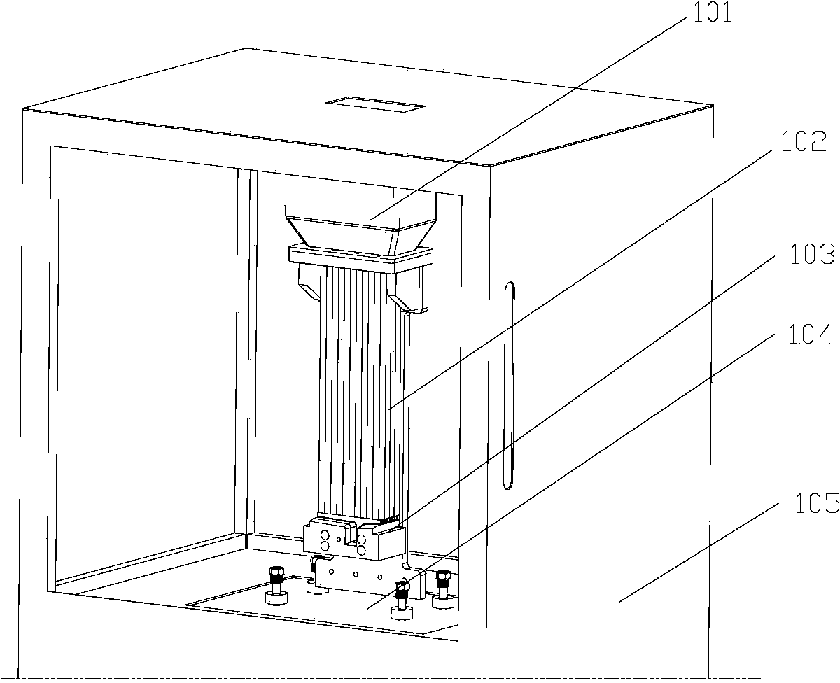
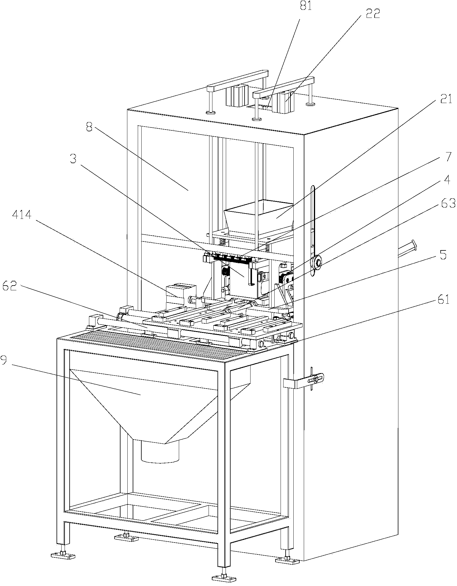
[0024] Please refer to Figure 3-Figure 6 , the lead-acid storage battery tubular plate powder filling device of the present application includes a powder filling chamber 8, a feeding mechanism, a pole plate fixing mechanism, a vibration seat 5 and a vibration source, and the powder filling chamber 8 is provided with a feed inlet 81 and a powder filling chamber 8. The chamber door and the feeding mechanism are provided with a material inlet and a material outlet. The material inlet is connected to the feed inlet 81, and the material enters the tubular pole plate from the material outlet. The pole plate fixing mechanism is fixed on the vibration seat 5, and the vibration seat 5 is installed on the On the vibration source in the powder filling chamber 8, the vibration source is preferably fixed on the bottom of the powder filling ...


PUM


Abstract

The application discloses a lead-acid storage battery tubular plate powder filling device which comprises a powder filling chamber, a feeding mechanism, a plate fixing mechanism, a vibration seat and a vibration source, wherein the powder filling chamber is provided with a feeding hole and a powder filling chamber door; the feeding mechanism is fixed in the powder filling chamber; the plate fixing mechanism is fixed on the vibration seat; the vibration seat is arranged on the vibration source in the powder filling chamber; the plate fixing mechanism comprises a mould box and a pressing mechanism; the pressing mechanism is used for fixing the mould box; the mould box is used for containing polar plates to be subjected to powder filling. The device can be applied to the field of lead-acid storage battery tubular plate powder filling. By adoption of the lead-acid storage battery tubular plate powder filling device, the polar plates are conveniently loaded and detached, the number of polar plates to be subjected to powder filling each time can be increased, and thus the production efficiency is improved. Moreover, the whole powder filling process is finished when the powder filling chamber door is closed, manual intervention is not needed, and thus dust pollution on an external environment is alleviated.

Description

technical field [0001] The application relates to the field of powder filling for lead-acid battery pole plates, in particular to a tube-type pole plate powder filling device for lead-acid battery. Background technique [0002] Tubular power lead-acid batteries, as the driving power of DC motors, have been widely used in airports, railway stations, ports, fruit and vegetable markets, warehouses and mines, etc. Vehicles that require pollution and zero emissions, such as traction vehicles, transport vehicles and mining vehicles, provide driving power. In addition, as people pay more attention to their own health and awareness of the hazards of environmental pollution, transportation equipment in some parks, sports and entertainment venues are also forced to use zero-pollution batteries. [0003] The tubular plate structure inside the tubular power lead-acid battery is as follows: figure 1 As shown, it is mainly composed of a grid 110, a protective pipe 111 and an active mate...

Claims


Application Information

Patent Timeline
Patent Type & Authority Applications(China)
IPC IPC(8): H01M4/16
CPCH01M4/0473H01M4/048H01M4/16Y02E60/10
Inventor 董捷郎小川陈国平
Owner ZHAOQING LEOCH BATTERY TECH
Why Eureka
Try Eureka