
Relay circuit, method thereof, controller local area network and CT device

A relay circuit and local area network technology, which is applied in the direction of bus network, data exchange through path configuration, data exchange details, etc., can solve problems such as inability to realize link communication

Active Publication Date: 2014-05-21
SIEMENS SHANGHAI MEDICAL EQUIP LTD
View PDF3 Cites 6 Cited by
  • Summary
  • Abstract
  • Description
  • Claims
  • Application Information

AI Technical Summary

Problems solved by technology

However, direct link communication cannot be realized between the nodes of such two isolated CAN networks, and MCU is required for processing and distribution

Method used


Image

  • Relay circuit, method thereof, controller local area network and CT device
  • Relay circuit, method thereof, controller local area network and CT device
  • Relay circuit, method thereof, controller local area network and CT device

Examples


Embodiment Construction

[0066] In order to make the purpose, technical solution and advantages of the present invention clearer, the following examples are given to further describe the present invention in detail.

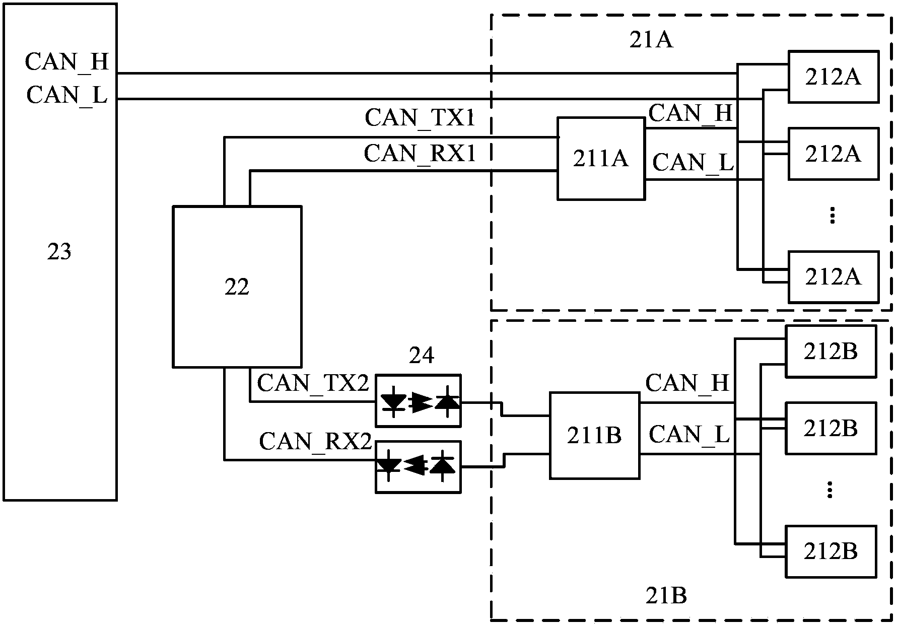
[0067] figure 2 is a schematic structural diagram of the CAN network according to the present invention. exist figure 2The CAN network shown in includes two CAN network parts (controller area network part): a first CAN network part 21A and a second CAN network part 21B. Each CAN network part includes a plurality of CAN terminals 212A, 212B connected by the CAN bus, and the CAN bus of each CAN network part 21A, 21B is connected with a CAN transceiver 211A, 211B, which is used for bus signal CAN_H, CAN_L and Transmit and receive signals CAN_TX1, CAN_RX1, CAN_TX2, CAN_RX2 for mutual conversion. CAN transceiver is a commonly used device in this field, and its function and usage method will not be described in detail here. The CAN transceiver 211B of the second CAN network part 21B is c...


PUM


Abstract

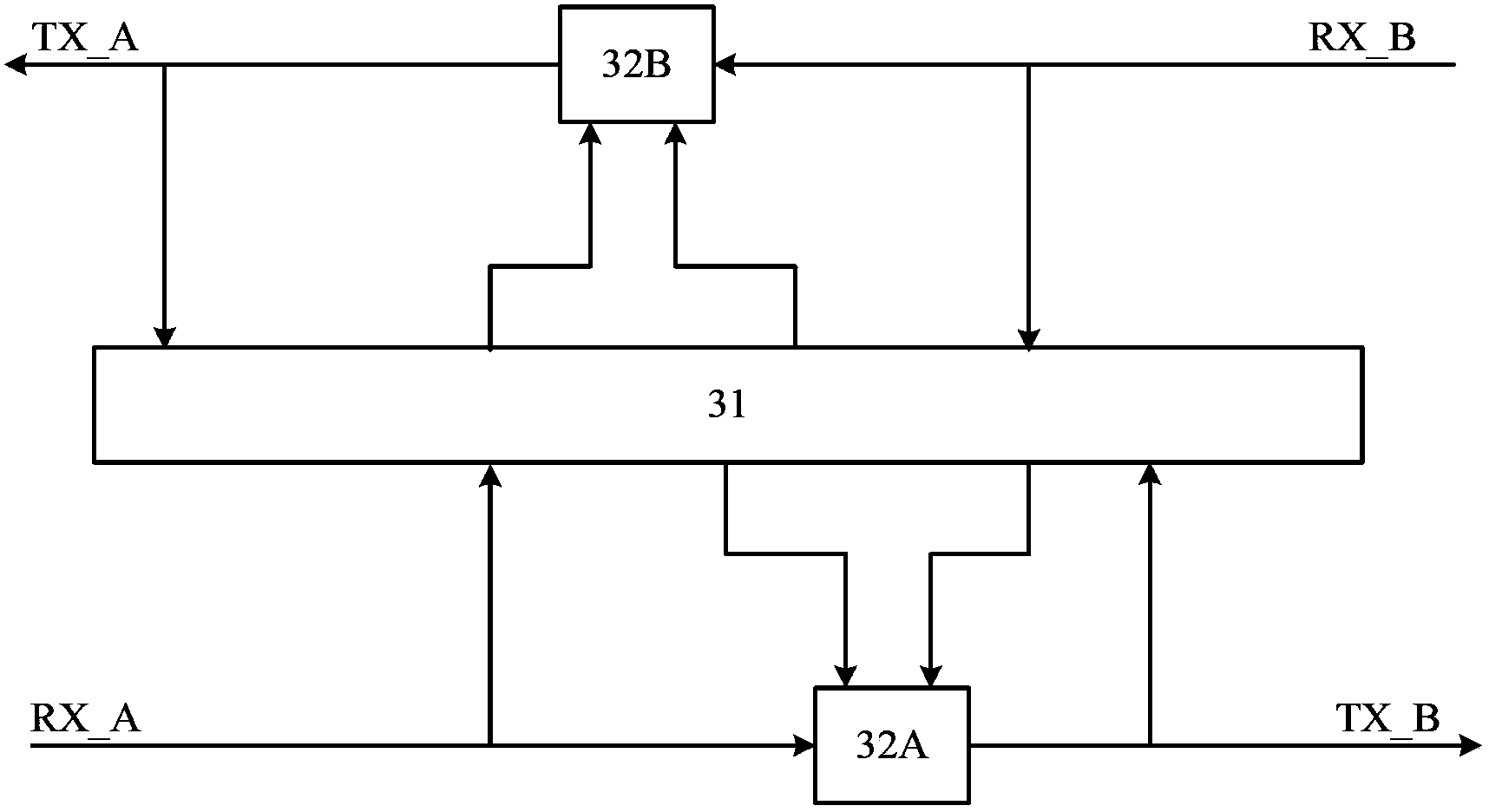
The invention provides a relay circuit used for a controller local area network, a method thereof, the controller local area network and a CT device. According to the relay circuit in the invention, when a receiving terminal at one side receives an explicit level firstly, the forwarding of a receiving terminal at another side to a sending terminal at a local side is locked, the explicit level is forwarded to the sending terminal of the other end, then when the the receiving terminal at the local side changes to a hidden level from the explicit level, the forwarding of the other receiving terminal to the sending terminal at the local end is started after the delay of a predetermined period, and when the receiving terminals at two ends receive explicit levels at the same time, the forwarding of the receiving terminal at the opposite side to the sending terminal at the local side is locked respectively. The relay circuit of the invention is preferably realized by a programmable logic chip and is preferably used in the field of the CT device.

Description

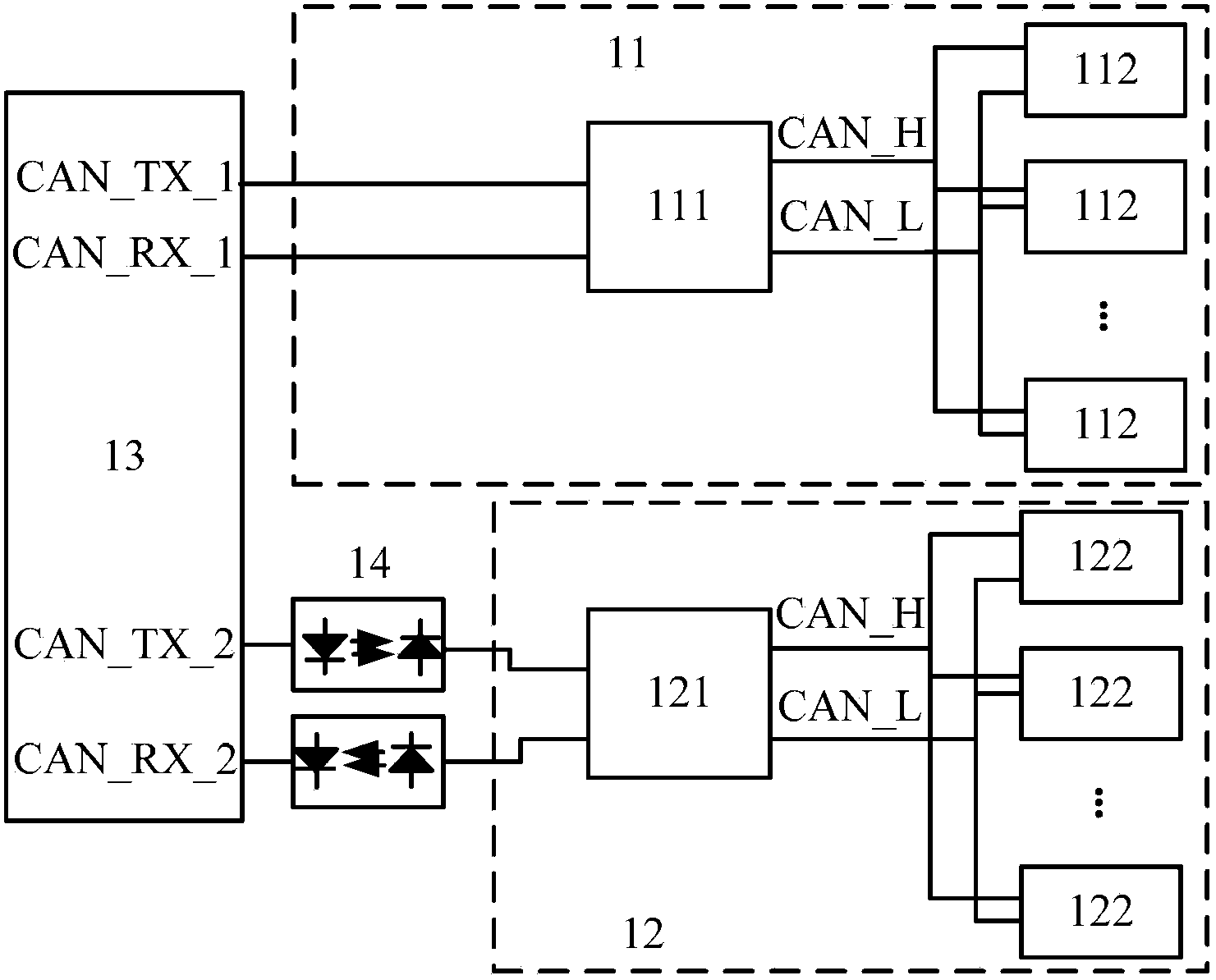
technical field [0001] The present invention relates to the field of control area network technology, in particular to a relay circuit and method for a controller area network (CAN), a controller area network using the relay circuit, and a controller area network using the controller area network Computed tomography (CT) equipment. Background technique [0002] In computer X-ray tomography (CT) equipment, the CAN bus is used to realize reliable communication between various components. Due to the electrical safety requirements of medical equipment, some CAN nodes need to be electrically isolated from other CAN nodes in the CAN bus network. [0003] At present, in CT equipment, in order to achieve electrical isolation between different CAN nodes, it is generally necessary to build two CAN networks, and the electrical isolation between the two CAN networks is achieved by optocouplers, such as figure 1 shown. figure 1 CAN networks 11 and 12 isolated by optocoupler devices 14...

Claims


Application Information

Patent Timeline
Patent Type & Authority Applications(China)
IPC IPC(8): H04L12/02H04L12/40
Inventor 刘兵杨儒珊
Owner SIEMENS SHANGHAI MEDICAL EQUIP LTD
Learn More