High-frequency boosting isolation inverter

A technology of step-up inverter and inverter, which is applied in the direction of high-efficiency power electronic conversion, conversion of AC power input to DC power output, output power conversion device, etc., which can solve the limitation of DC side input voltage, limited circuit energy transmission, Low voltage utilization rate and other issues, to achieve the effect of reducing input current ripple, improving core utilization rate, and short resonance time

Inactive Publication Date: 2013-11-20
ZHEJIANG UNIV
View PDF4 Cites 13 Cited by
  • Summary
  • Abstract
  • Description
  • Claims
  • Application Information

AI Technical Summary

Problems solved by technology

However, the double Buck inverter has the following disadvantages: the voltage stress of the power tube is twice that of the output voltage, and its voltage utilization rate is low; the output voltage waveform of the bridge arm is bipolar, and the harmonic content is large
But the disadvantage of this circuit is that the switch tube has to bear the voltage stress of 3 to 5 times the DC bus, the input voltage of the DC side is limited, and the energy transmission of the circuit is limited.

Method used


Image

  • High-frequency boosting isolation inverter
  • High-frequency boosting isolation inverter
  • High-frequency boosting isolation inverter

Examples


Embodiment Construction

[0031] In order to describe the present invention more specifically, the technical solutions and related working principles of the present invention will be described in detail below in conjunction with the accompanying drawings and specific embodiments.

[0032] Such as Figure 5 As shown, a high-frequency step-up isolation inverter includes a high-frequency step-up inverter circuit and an AC-AC conversion circuit; wherein:

[0033] The high-frequency step-up inverter circuit is used to convert the input DC voltage V in converted into a single-phase AC voltage; in this embodiment, the high-frequency boost inverter circuit includes two coupled inductors L 1 ~ L 2 , two clamp switches S c1 ~S c2 , two clamping capacitors C c1 ~C c2 , two main switches S 1 ~S 2 , a filter inductor L k and a resonant capacitor C o ;in:

[0034] Coupled inductor L 1 Primary winding L 1a The non-dotted end of the coupled inductor L 2 Primary winding L 2a The non-identical end is conn...


PUM


Abstract

The invention discloses a high-frequency boosting isolation inverter, which comprises a high-frequency boosting inverting circuit and an AC-AC (alternating current-alternating current) conversion circuit. The high-frequency boosting inverting circuit is mainly used for outputting the single-phase AC voltage, and realizing the low ripple of input current by controlling the phase of the main switch tube via a staggered parallel connecting structure. Meanwhile, the high-frequency boosting inverting circuit adopts an active clamp structure to realize soft opening and closing of the main switch tube, so the consumption is reduced and the efficiency is improved. In addition, the high-frequency boosting inverting circuit adopts two coupled induction type serial connecting structures at the load side to realize higher boosting capability. The single-phase AC voltage is converted into the three-phase AC current by the AC-AC conversion circuit, and the energy transmission process is divided into a capacitance side charging part and a capacitance side discharging part for the output end. Therefore, the isolation inverter can obtain higher voltage gain and lower input current ripple, and the conversion efficiency and the reliability are high.

Description

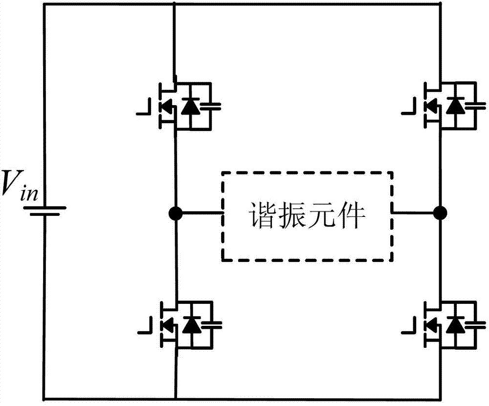
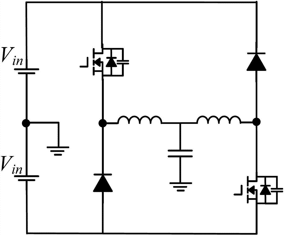
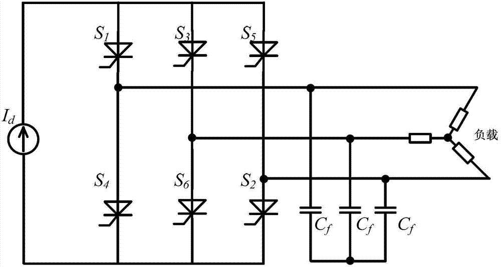
technical field [0001] The invention belongs to the technical field of power electronics, and in particular relates to a high-frequency step-up isolation inverter. Background technique [0002] The traditional DC-AC inverter needs to go through a bridge circuit, such as figure 1 Shown; This kind of bridge inverter because of the poor performance of the body diode of the switching tube, it causes a lot of loss and limits the improvement of the switching frequency. At the same time, the bridge circuit also has the danger of direct connection between the upper and lower power tubes of the same bridge arm. In order to overcome this danger, a double Buck inverter and a current source inverter are respectively proposed. [0003] Dual Buck inverters such as figure 2 As shown, it consists of two Buck circuits. Due to the existence of two inductors, it overcomes the direct problem of the traditional bridge-type inverter bridge and does not need to set the dead time. In addition, ...

Claims


Application Information

Patent Timeline
Patent Type & Authority Applications(China)
IPC IPC(8): H02M7/537
CPCY02B70/1491Y02B70/10
Inventor 胡义华邓焰王晓明李楚杉赵鑫宇邹智渊杨洁
Owner ZHEJIANG UNIV
Why Eureka
Try Eureka