Electrodialysis partitioning plate

A technology of electrodialysis and separator, which is applied in the field of electrodialysis, can solve the problems of increased equipment cost, reduced effective area of ​​membrane, and reduced water channel area in the center of the separator, so as to achieve the effect of increasing sealing performance and sparse distribution of water distribution channels

Inactive Publication Date: 2014-05-28
ZHEJIANG GONGSHANG UNIVERSITY
View PDF10 Cites 7 Cited by
  • Summary
  • Abstract
  • Description
  • Claims
  • Application Information

AI Technical Summary

Problems solved by technology

This patent reduces the number and density of water distribution channels to prevent the selective membrane from sinking and leaking when it is attached to the separator. Because the water distribution channels are reduced, the processing capacity of the device is also greatly reduced
[0007] 2. Energy loss caused by leakage current. During the normal operation of the electrodialysis device, there is also a certain current in the water flow in the water distribution channel. This part of the current (called leakage current or parasitic current) does not contribute to desalination, but causes There is a certain relationship between the energy loss and the current size and the len

Method used


Image

  • Electrodialysis partitioning plate
  • Electrodialysis partitioning plate
  • Electrodialysis partitioning plate

Examples


Example Embodiment

[0028] Example 1

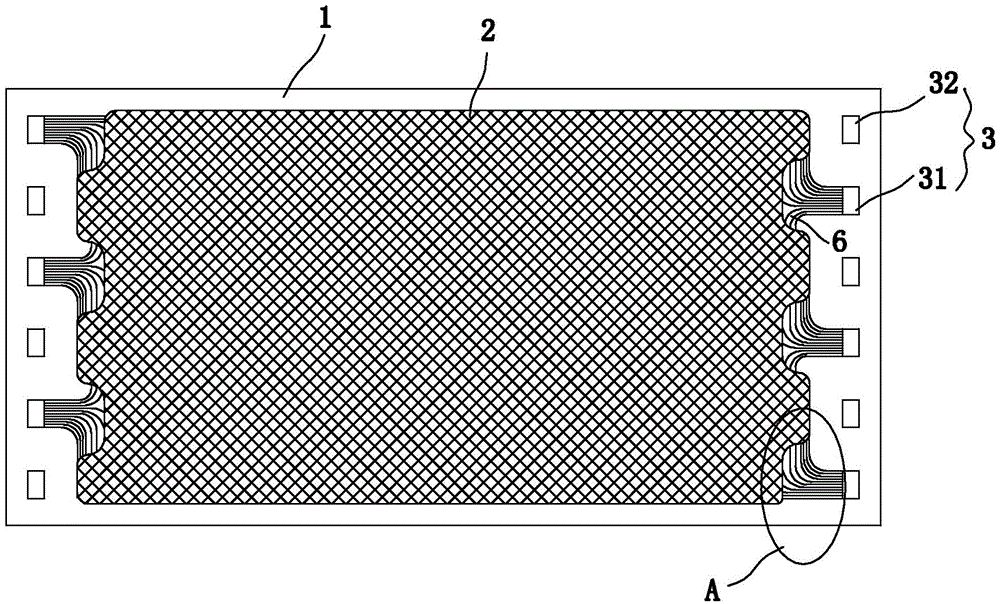
[0029] Such as Figure 1~3 As shown, an electrodialysis separator includes a plate frame 1 with a size of 200×400mm. The plate frame 1 is made of EVA resin and has a thickness of approximately 0.85mm. The central cavity is provided with a partition net 2 made of pp, the thickness is 0.80mm.

[0030] The upper and lower ends of the plate frame 1 are provided with liquid guiding holes 3, and the liquid guiding holes 3 are divided into two groups, one of which is an open liquid guiding hole 31 communicating with the central cavity of the current layer of the plate frame through the water distribution channel 4, and the other One group is a closed liquid guiding hole 32 that does not communicate with the central cavity of the current layer frame, and the open liquid guiding hole 31 and the closed liquid guiding hole 32 are spaced apart. The shape of the liquid guiding hole 3 in this embodiment is rectangular, and the size is 20×10 mm, and it may also be round or ov...

Example Embodiment

[0039] Example 2

[0040] Use 20 pairs of 200×400mm homogeneous ion exchange membranes, and 40 electrodialysis separators with 15% vinyl acetate content, and assemble them into a membrane stack according to the installation sequence of the electrodialysis membrane stack. The inlet water concentration of the concentration chamber is 1000mg / The flow rate of L NaCl solution is 0.5m3 / h, the test voltage is 30V direct current, the inlet pressure of the membrane stack is 0.05MPa, the test shows that the membrane stack runs for a long time without leakage, and the primary desalination rate of the membrane stack reaches 39% .

Example Embodiment

[0041] Example 3

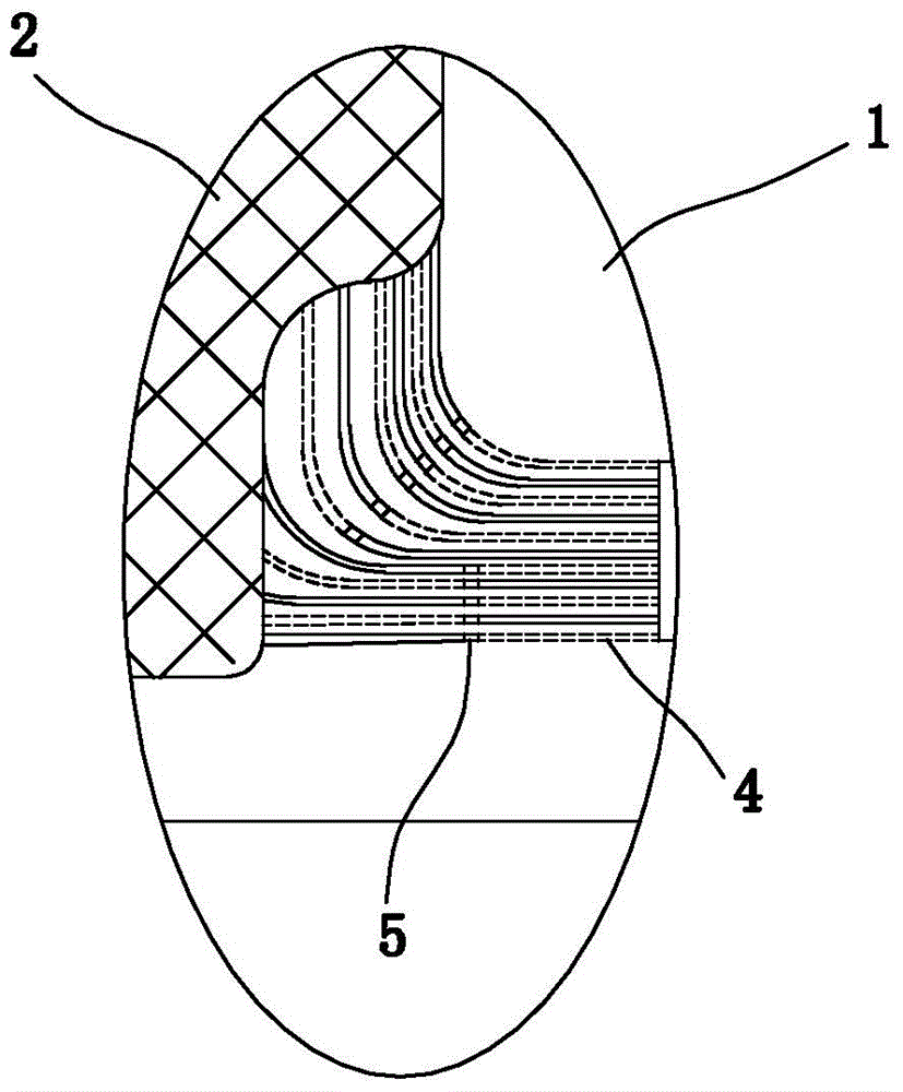
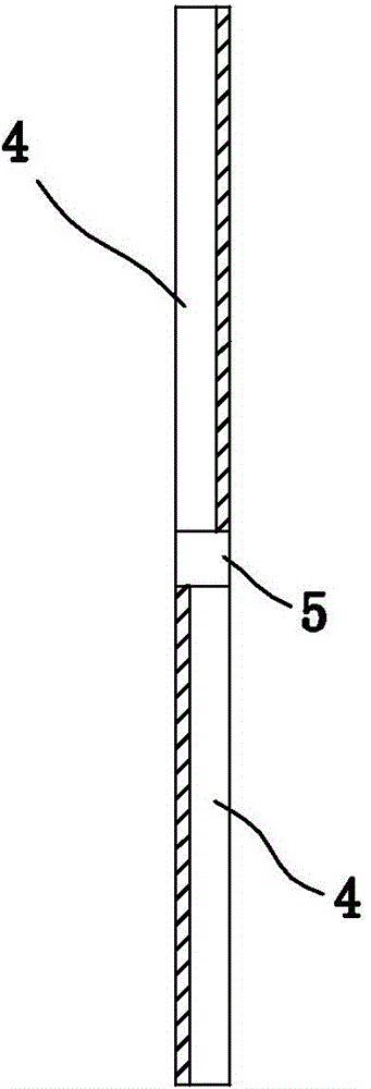
[0042] The partition is 800mm long and 400mm wide. The frame 1 is made of EVA sheet with a vinyl acetate content of 15%, and the thickness is 0.9mm. The thickness of the screen 2 is 0.80mm. The liquid guide holes 3 are 6 rectangular holes of 25×15mm, and each open liquid guide hole 31 corresponds to 12 water distribution channels 4 with a depth of 0.72mm, the length of the perforation 5 is 1.5mm, and the initial width of the water distribution channel 4 The width of the curved part after the arc is increased to 1.5mm, the distance between adjacent water distribution channels in the initial section is 1.2mm, and the distance between the edge of the protrusion 6 and the end of the frame 1 is 90mm, and the rest is the same as in Example 1.

[0043] The membrane stack was formed according to the method of Example 1. The inlet water concentration of the concentration chamber is 1000mg / L NaCl solution, and the flow rate is 1m. 3 / h, the test voltage is 30V direct curre...


PUM


Abstract

The invention discloses an electrodialysis partitioning plate which comprises a plate frame, wherein liquid guide holes and water distribution channels for communicating the liquid guide holes with a central cavity of the plate frame are formed in the plate frame; each water distribution channel is at least divided into two sections; multiple sections of the water distribution channels are arranged on two side surfaces of the plate frame in a cross manner; two adjacent sections of the water distribution channels are communicated through the through holes in the plate frame. As each water distribution channel is divided into multiple sections, and the sections are arranged on the two side surfaces in the cross manner, the sealing capability of an ion exchange film and the partitioning plate is improved under the condition that the same number of water distribution channels are formed.

Description

technical field [0001] The invention relates to the technical field of electrodialysis, in particular to an electrodialysis separator. Background technique [0002] Electrodialysis is a kind of membrane separation technology. It uses the potential difference as the driving force under the action of a direct current electric field to separate the electrolyte from the solution by using the selective permeability of the ion exchange membrane, thereby realizing the desalination and concentration of the solution. , refined or purified. The electrodialysis separator is one of the necessary parts of the electrodialysis device. Its function is to directly create a certain gap between the anion membrane and the anode membrane to form a concentration compartment, and provide the water flow and current of the compartment for the normal operation of the electrodialysis unit. conduction. [0003] Generally speaking, when designing an electrodialysis separator, the following two factors...

Claims


Application Information

Patent Timeline
IPC IPC(8): B01D61/50C02F1/469
Inventor 吴春金周慧婷杜春慧吴礼光
Owner ZHEJIANG GONGSHANG UNIVERSITY
Why Eureka
Try Eureka