Frame-integrated multi-rod guide continuous zoom device

A frame and screw technology, applied in the field of precision instruments, can solve problems such as image shaking, and achieve the effect of eliminating connection gaps, improving environmental adaptability and good rigidity

Active Publication Date: 2015-09-09
HUBEI JIUZHIYANG INFRARED SYST CO LTD
View PDF6 Cites 2 Cited by
  • Summary
  • Abstract
  • Description
  • Claims
  • Application Information

AI Technical Summary

Problems solved by technology

At present, this kind of mechanism is mostly used in a short stroke (≤60mm), and because the connection between the guide rod and the lens group uses a linear bearing, due to its own characteristics, there must be a small gap. The gap transferred to the lens group will be magnified, causing the image to shake

Method used


Image

  • Frame-integrated multi-rod guide continuous zoom device
  • Frame-integrated multi-rod guide continuous zoom device
  • Frame-integrated multi-rod guide continuous zoom device

Examples


Embodiment 1

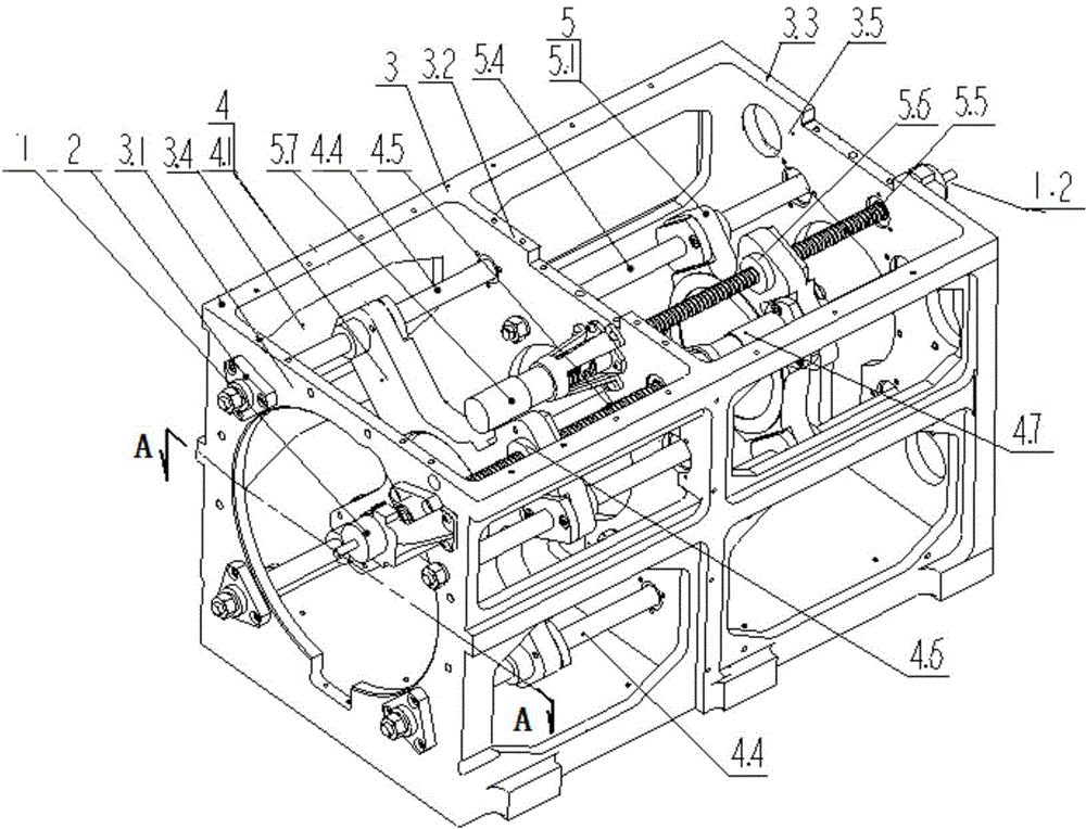
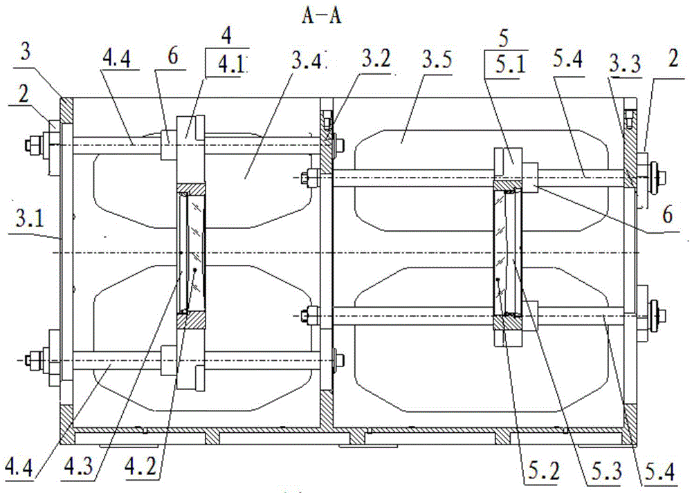
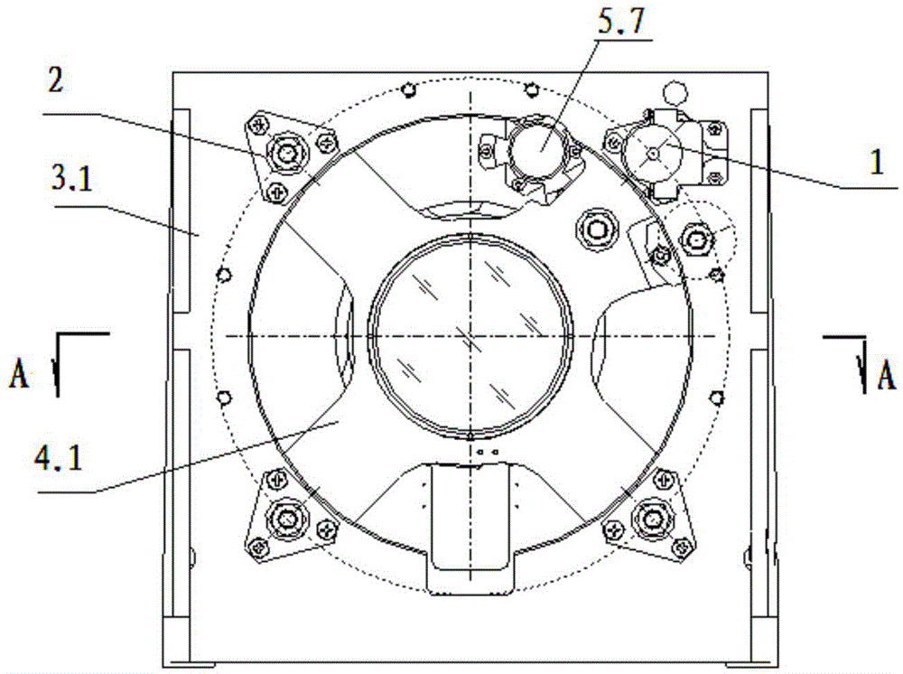
[0024] Example 1: for the basic example. Such as Figure 1-6 As shown, a frame-integrated multi-rod guiding continuous zoom device includes a frame 3 with two chambers, the frame 3 is a whole, and the chamber on one side of the middle vertical wall 3.2 is a zoom lens chamber 3.4, which is installed Comprising a zoom lens group 4 of a zoom lens 4.2, the chamber on the other side is a compensation lens chamber 3.5, which is installed with a compensation lens group 5 including a compensation lens 5.2; the zoom lens group 4 includes a zoom lens The seat 4.1 is installed with at least three linear bearings 6 for supporting the variable power lens seat 4.1 and one variable power lens seat screw nut 4.6 for driving the variable power lens seat 4.1 to move linearly; The variable power lens group guide rod 4.4 and the variable power lens group screw rod 4.5 passing through the variable power lens seat screw nut 4.6 are respectively connected to the variable power lens chamber wall 3...

Embodiment 2

[0025] Example 2:as a further example. The difference from Embodiment 1 is that the variable magnification encoder 1 is fixed on the variable magnification lens chamber wall 3.1 with its outer casing through an encoder pressure ring 9 and an encoder bracket 10; the compensation encoder 1.2 is fixed with its outer casing The body is fixed on the compensation lens chamber wall 3.3 via an encoder pressure ring 9 and an encoder holder 10. The linear bearing 6 for supporting the zoom lens seat 4.1 and the screw nut 4.6 of the zoom lens seat are fixedly connected with the zoom lens seat 4.1 by screws; the linear bearing 6 and the compensation lens seat for supporting the compensation lens seat 5.1 The screw nut 5.6 is fixedly connected with the compensating lens seat 5.1 by screws. The zoom lens 4.2 is fixed in the middle of the zoom lens seat 4.1 through the zoom lens ring 4.3; the compensation lens 5.2 is fixed in the middle of the compensation lens seat 5.1 through the compens...


PUM


Abstract

The invention relates to a frame integration type multi-rod guiding continuous zooming device which comprises a frame with two cavities. The frame is a whole. A zooming lens group and a compensation lens group are arranged in the cavities. At least three straight line bearings and a zooming lens base lead screw nut are arranged on a zooming lens base. One end of a zooming lens base lead screw is connected with a zooming driving motor, and the other end of the zooming lens base lead screw is inserted into a zooming encoder. At least three straight line bearings and a compensation lens base lead screw nut are arranged on a compensation lens base. One end of a compensation lens base lead screw is connected with a compensation driving motor, and the other end of the compensation lens base lead screw is inserted into a compensation encoder. The zooming driving motor and the compensation driving motor are fixed on stand walls respectively. The frame integration type multi-rod guiding continuous zooming device has the advantages that whole rigidness is good, accuracy is high, images are stable under vibration conditions, the whole device is high in environment adaptability, multi-rod guiding is used for achieving the coaxality of moving, the structure technology is good, machining is easy, adjustment accuracy is improved, and the optical axis consistence during guiding lens moving is guaranteed.

Description

technical field [0001] The invention relates to a frame-integrated multi-rod guiding continuous zoom device, which belongs to the technical field of precision instruments, and is a device for realizing mutual motion relationship between a zoom lens group and a compensation lens group in the axial direction. Background technique [0002] In the long focal length continuous zoom optical system, the stability of the motion relationship between the zoom lens and the compensation lens is a key part of the success of the continuous zoom optical system. In the usual continuous zoom system, the cam mechanism is used to realize the movement of the zoom lens group and the compensation lens group. The disadvantages of the cam mechanism are easy to stick, poor optical axis consistency, low control precision, and high difficulty in cam processing. For the long focal length continuous zoom system, due to the longer strokes of the zoom group and the compensation group, higher requirements ...

Claims


Application Information

Patent Timeline
Patent Type & Authority Patents(China)
IPC IPC(8): G02B7/04
Inventor 王波郭良贤熊涛刘明群李彪
Owner HUBEI JIUZHIYANG INFRARED SYST CO LTD
Why Eureka
Try Eureka