Harmonic suppression method for automatic voltage control system

A control system and harmonic suppression technology, applied in harmonic reduction devices, AC networks to reduce harmonics/ripple, reactive power compensation, etc., can solve problems such as equipment abnormality, unreasonable switching of capacitors, and economic losses Achieve the effect of reducing equipment action delay, optimizing equipment action times, and reducing equipment damage accidents

Active Publication Date: 2014-05-28
STATE GRID CORP OF CHINA +1
View PDF2 Cites 3 Cited by
  • Summary
  • Abstract
  • Description
  • Claims
  • Application Information

AI Technical Summary

Problems solved by technology

[0003] There are many harmonic sources and reactive power impact loads in the regional power grid, and due to various reasons such as unreasonable configuration of reactive power sources in the actual power grid, changes in operation mode, unreasonable program algorithms, etc., it is easy to cause on-site capacitors to be invested Cut too frequently, causing damage to some capacitors and their switches, resulting in certain economic losses and equipment abnormalities
In addition, due to the unreasonable and non-targeted algorithm, the switching of on-load transformer taps and capacitors is unreasonable, which leads to unreasonable distribution of reactive power in the power grid, reverse distribution of voltage adjustment pass rate, etc.
[0004] like figure 2 As shown, in the traditional AVC control method, when the voltage exceeds the limit, switching the capacitor (reactor) and adjusting the gear of the transformer will eliminate the voltage limit, but the impact on the reactive power flow is different. The traditional voltage and reactive power adjustment strategy Strategy selection based on static section data without considering load variations
Existing power grid AVC often only considers the current time section of the power system, without considering historical experience and future trends. Therefore, frequent switching of equipment, low utilization of equipment, etc. are inevitable, and the number of equipment operations cannot be optimized.

Method used


Image

  • Harmonic suppression method for automatic voltage control system
  • Harmonic suppression method for automatic voltage control system
  • Harmonic suppression method for automatic voltage control system

Examples


Embodiment Construction

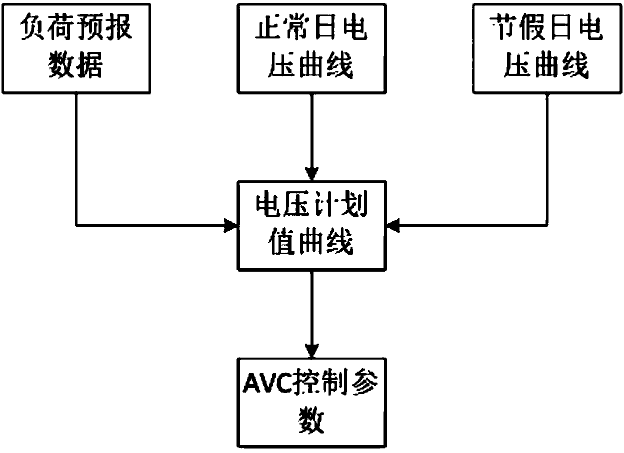
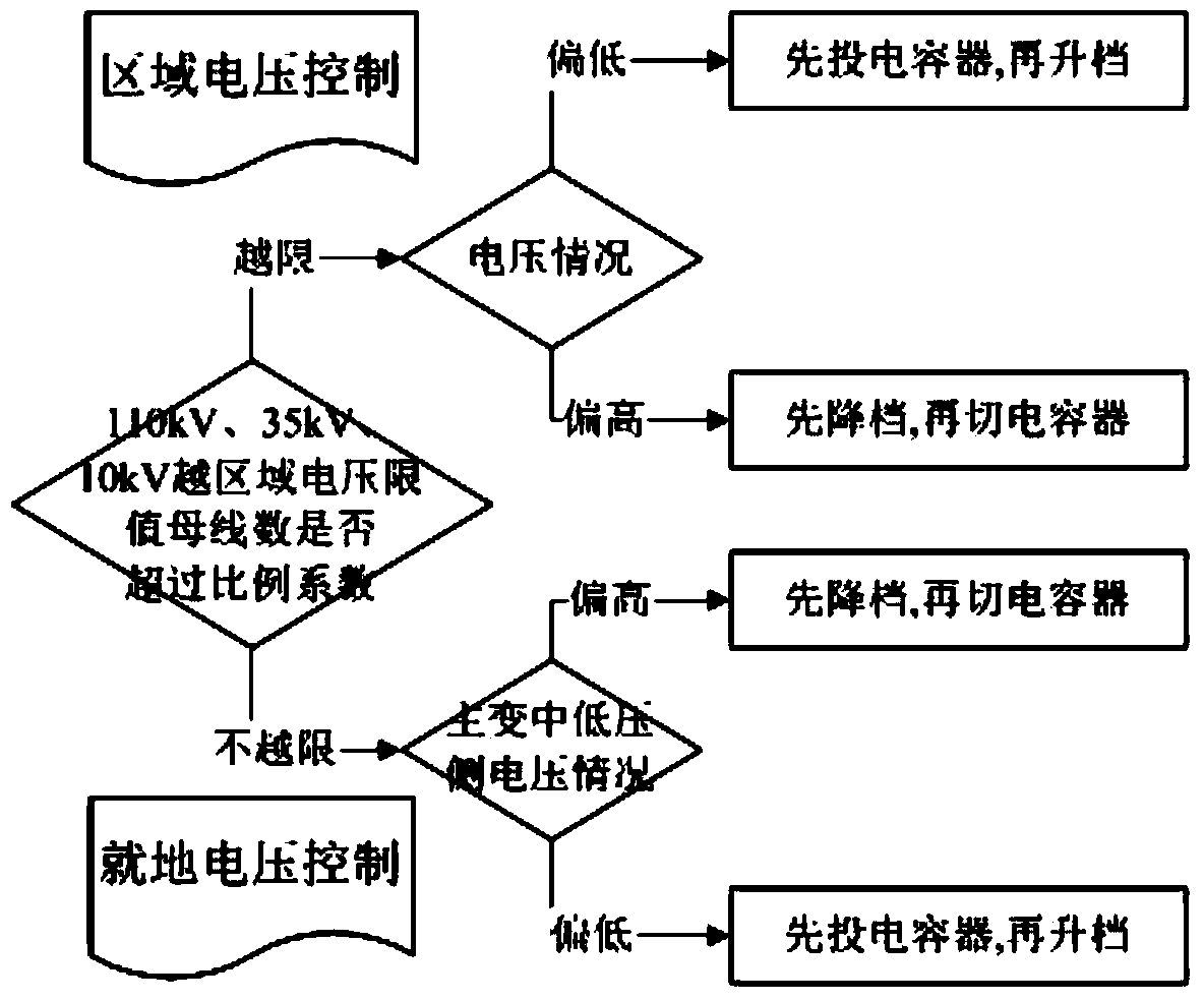
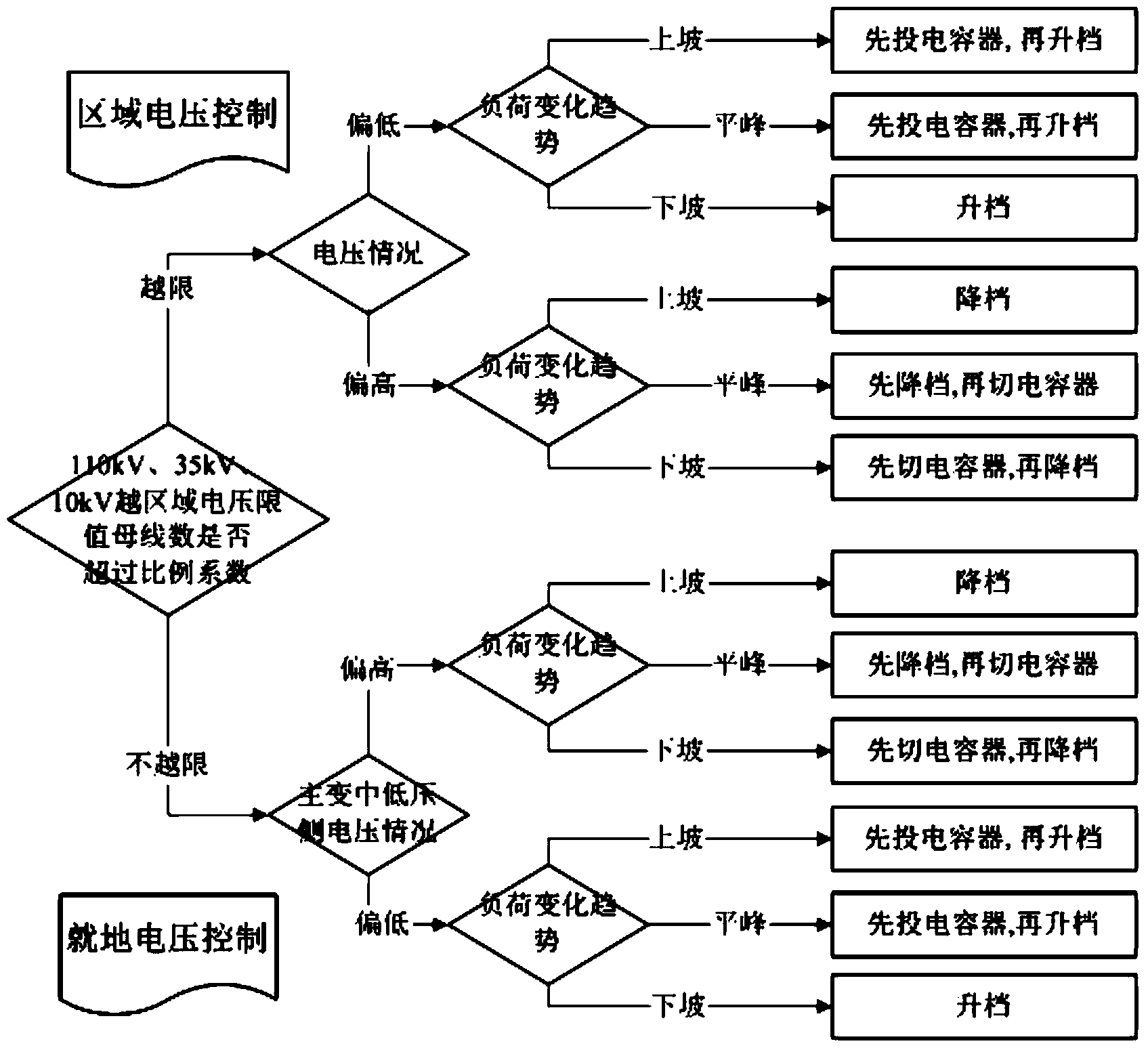
[0019] Based on the traditional AVC control strategy, the present invention comprehensively considers the load change trend on the basis of the hierarchical and partitioned control strategy, and adds the electrical control attribute diagnosis link of the current state of the transformer tap and capacitor / reactor group, and proposes a method based on optimizing the number of equipment actions The AVC control strategy makes the control strategy predictable, realizes advanced control according to the operating status of the equipment, optimizes the number of equipment actions in the entire time sequence, and improves the utilization rate of the equipment, which is of great significance to improving the service life of the equipment.

[0020] Theoretically, the distribution of reactive power can be optimal, and the optimization of reactive power flow is to optimize the reactive power flow of the power grid. However, it is almost impossible to realize it online in the complex power ...


PUM


Abstract

The invention discloses a harmonic suppression method for an automatic voltage control system. A hierarchical partitioning control strategy is additionally arranged on the conventional automatic voltage control (AVC) system, and a charge prediction process and an electrical control property diagnosis process for considering the current state of equipment are added, so that the control strategy is predictable; meanwhile, advanced control is realized according to a running state of the equipment, and operation time delay of the equipment is reduced. An experiment result shows that the system has better effects of improving the voltage qualified rate of a power grid and optimizing the reactive power. The novel system optimizes the equipment operation frequency in the whole time sequence, so that the equipment damage accidents caused by frequent operation of the equipment are obviously reduced, and the service life of the equipment is prolonged.

Description

technical field [0001] The invention relates to a harmonic suppression technology based on the traditional automatic voltage control system (AVC). Background technique [0002] Voltage quality, as one of the important indicators to measure the quality of power system operation, has an important impact on ensuring the safe use of electrical equipment and product quality. With the rapid development of power system automation and communication technology, the application of automatic voltage control (AVC) technology based on EMS / SCADA system is becoming more and more common. good technical means. [0003] There are many harmonic sources and reactive power impact loads in the regional power grid, and due to various reasons such as unreasonable configuration of reactive power sources in the actual power grid, changes in operation mode, unreasonable program algorithms, etc., it is easy to cause on-site capacitors to be invested Cut too frequently, causing damage to some capacito...

Claims


Application Information

Patent Timeline
Patent Type & Authority Applications(China)
IPC IPC(8): H02J3/01H02J3/18
CPCY02E40/30Y02E40/40
Inventor 林其友任水华王刘芳杜磊李涛
Owner STATE GRID CORP OF CHINA
Why Eureka
Try Eureka