

Video image rotation method
A video image and image technology, which is applied in the field of airborne video display, can solve problems such as slow processing speed, large buffer areas, and holes in rotating images, and achieve the effects of being suitable for hardware implementation, reducing buffer space, and improving real-time performance
- Summary
- Abstract
- Description
- Claims
- Application Information
AI Technical Summary
Problems solved by technology
Method used
Image

Examples
Embodiment 1
[0046] In this embodiment, the video image is rotated counterclockwise by θ°, where 0<θ≤45. Use the jth and j+1th lines to process the coordinates before rotation, and obtain the corresponding video rotation processing results.
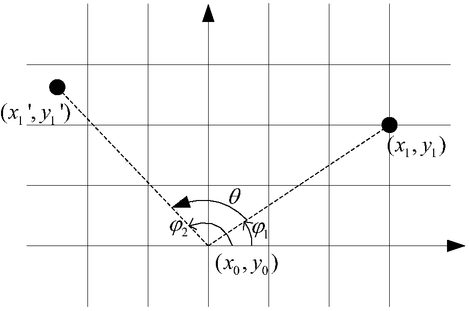
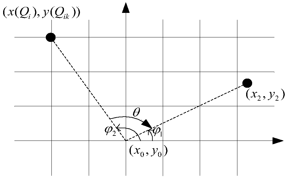
[0047] Figure 2a It is a schematic diagram of forward rotation mapping, and the image coordinates before rotation are set as (x 1 ,y 1 ), each pixel image in each row revolves around the center of the screen (x 0 ,y 0 ) after rotating the angle θ counterclockwise, the coordinates of the rotated image are obtained as (x 1 ',y 1 '). The formula is:
[0048] x 1 ′ = ( x 1 - x 0 ) cos ...
Embodiment 2
[0064] In this embodiment, the video image is rotated counterclockwise by θ°, where -45≤θ<0. Use the jth and j+1th lines to process the coordinates before rotation, and obtain the corresponding video rotation processing results.
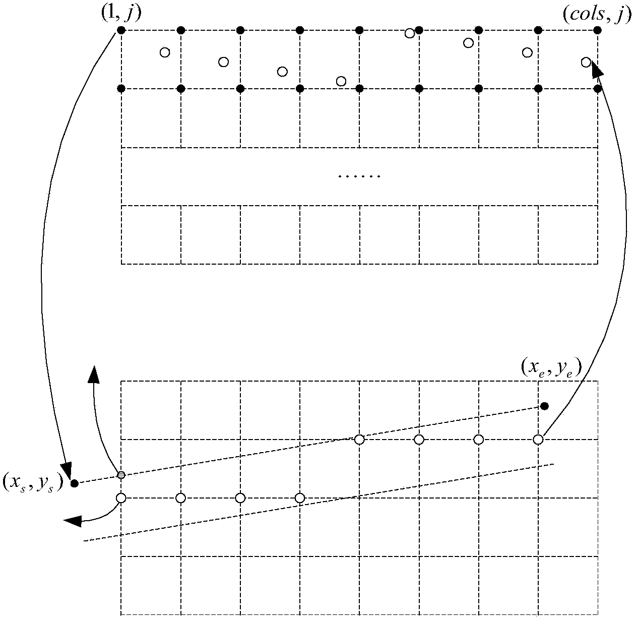
[0065] Forward mapping the first and last coordinates (1,j), (cols,j) of row j to the corresponding rotated floating-point coordinates (x s ,y s ),(x e ,y e ),but:
[0066] x s = ( 1 - x 0 ) * cos θ - ( j - y 0 ...
PUM
 Abstract
Description
Claims
Application Information