Caterpillar band guiding and derail preventing rail clamping device

A technology of crawler and rail clamp, which is applied in the directions of crawler vehicles, transportation and packaging, motor vehicles, etc., can solve the problems of insufficient shear strength, failure of rail clamps, and excessive clearance.

Active Publication Date: 2014-06-04
CHTC JOVE HEAVY IND
View PDF5 Cites 4 Cited by
  • Summary
  • Abstract
  • Description
  • Claims
  • Application Information

AI Technical Summary

Problems solved by technology

[0006] (1) Foreign matter gets stuck between the guide plate of the rail clamp and the track chain rail, causing the rail clamp to open outwards and fail
[0007] (2) Foreign objects are stuck between the track chain rail and the rail clamp or the bolts are loose. When the tonnage of the machine is too large, the bolts connecting the rail clamp and the track side beam bottom plate have insufficient shear strength and break
[0008] (3) After the stopper is worn out, the gap

Method used


Image

  • Caterpillar band guiding and derail preventing rail clamping device
  • Caterpillar band guiding and derail preventing rail clamping device
  • Caterpillar band guiding and derail preventing rail clamping device

Examples


Embodiment 1

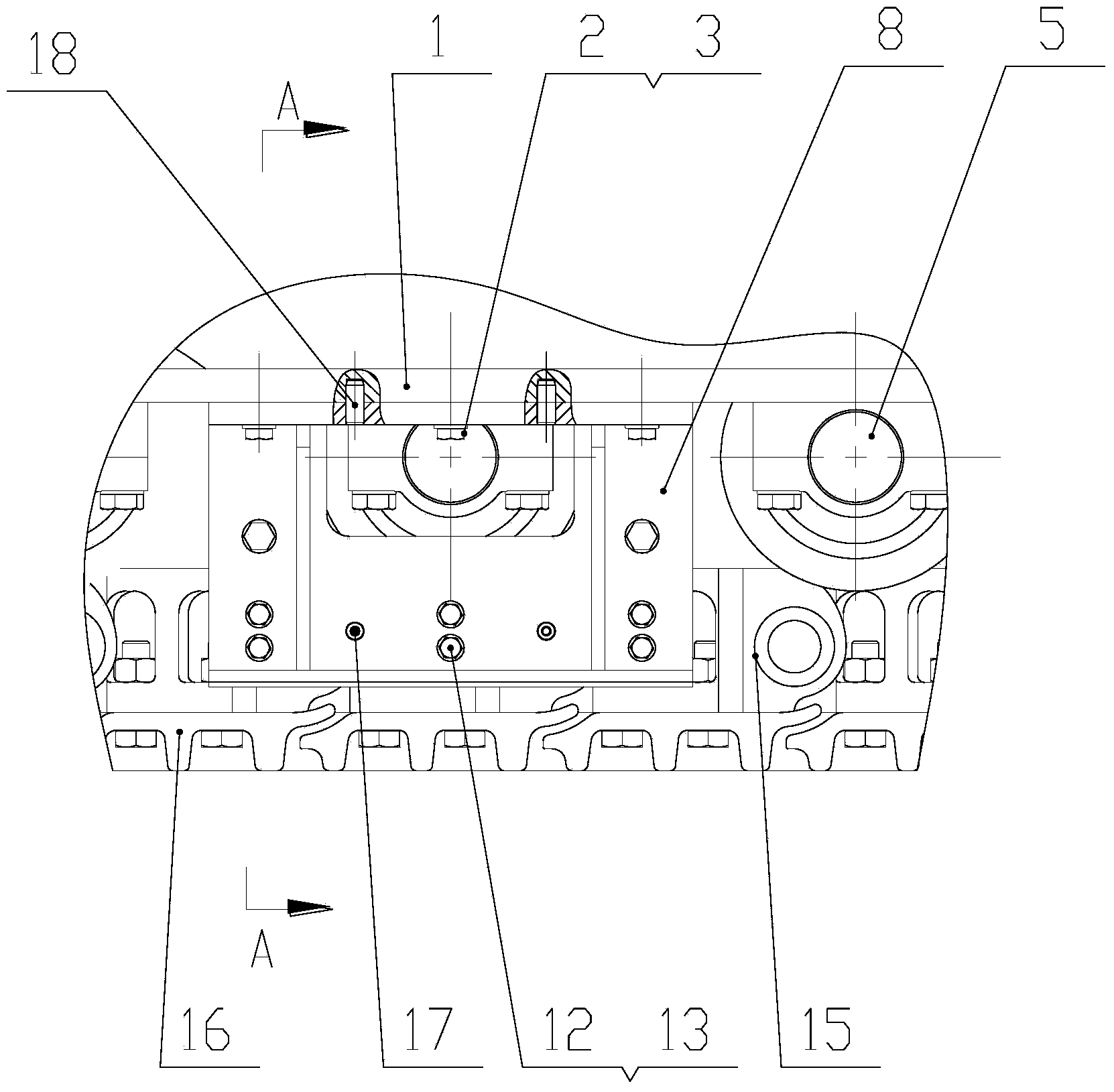
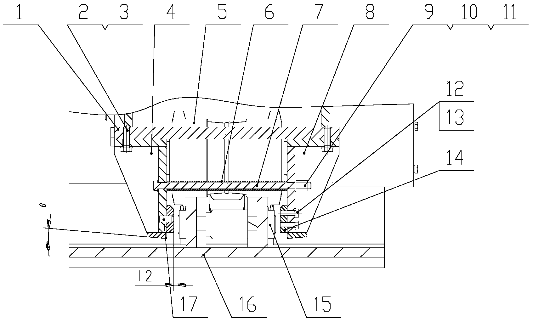
[0034] like Figure 1-3 As shown, the clamper of this embodiment is a rail clamping device for construction machinery chassis using a crawler walking device. It specifically relates to the connection between the bottom surface of the side beam 1 of the construction machinery chassis using crawler belts by connecting the first connecting bolt 2 and the first elastic washer 3, and symmetrical installation at the installation positions of multiple rail clamps on the bottom surface of the side beam 1 of the construction machinery chassis. The point rail clamps of the left rail clamp 4 and the right rail clamp 8 are located on both sides of the track roller 5 and the chain rail wheel of the crawler construction machinery. In order to ensure that the left rail clamp 4 and the right rail clamp 8 is subjected to external force and shears and destroys the connecting bolt 2, and a connecting positioning pin 18 is designed in the connection between the chassis side beam 1 and the left ra...

Embodiment 2

[0039] In order to eliminate the installation of many pairs of left rail clamps 4 and right rail clamps 8, the size of the clamping rail gap L2 is different, and there are errors. The overall structure of the half "I" character formed by the side plate, the length of the side plate, the upper plate and the lower plate is 70-90% of the ground length of the construction machinery chain rail, and there are multiple pairs of tie rods at intervals in the length direction of the side plate Holes, perpendicular to the side panels are provided with stiffeners near the holes of each tie rod. There is a circular arc transition between the upper plate and the lower plate. The rail clamp of the present embodiment is a surface rail clamp of the above-mentioned left rail clamp 4 and right rail clamp 8 installed on the bottom surface of the side beam 1 of the engineering machinery chassis. The axial limiting plate is at least three partially protruding reinforcing ribs arranged in parallel ...

Embodiment 3

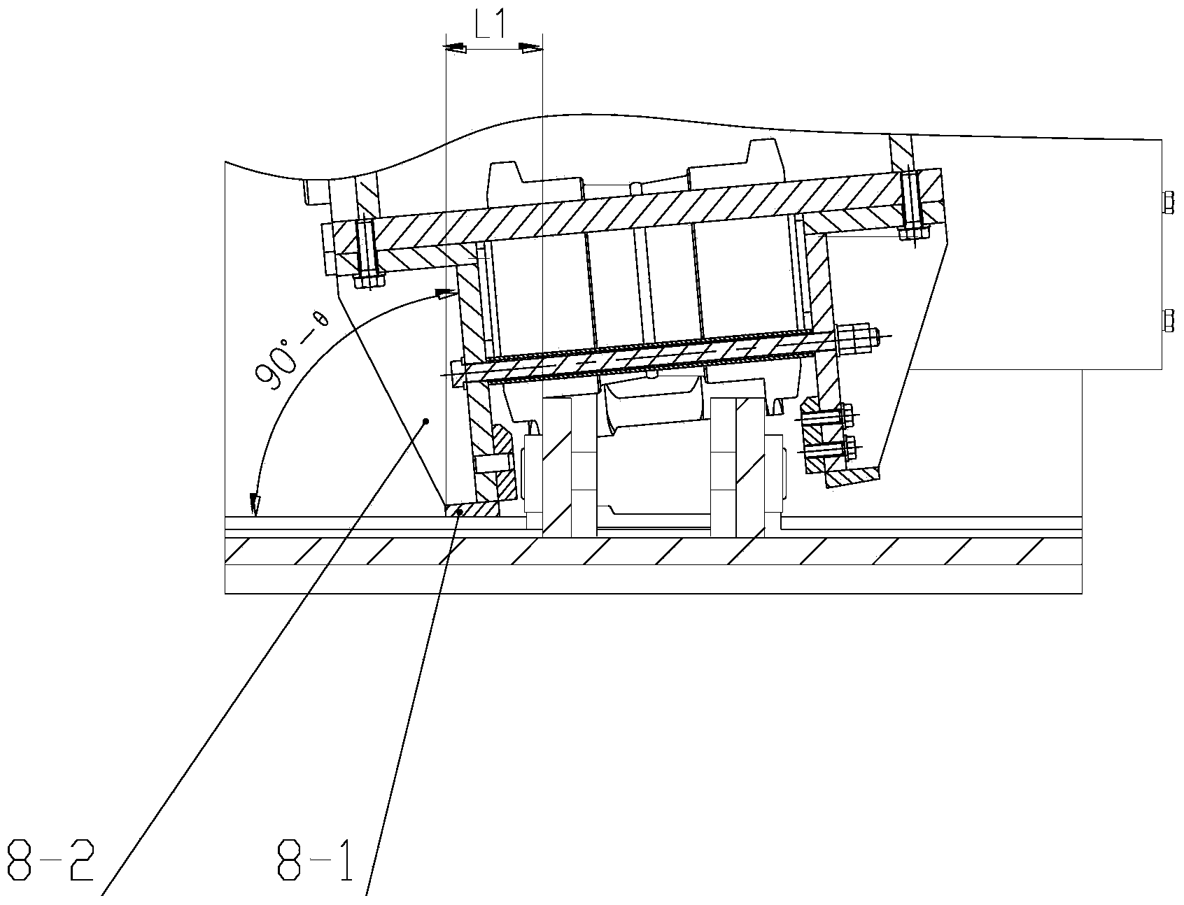
[0041] like Figure 4 , 5 As shown, the improvement of this embodiment is that the thickness of the axial limit plate 8-4 is a gradual shape with a thick top and a thin bottom, and the inclination angle θ of the clamping rail thickness 1 Defined as the angle between the two sides of the axial limit plate 8-4, the inclination angle θ of the clamp rail thickness 1 It is equal to the inclination angle θ between the track shoe and the track shoe when the lower plate of the rail clamp is installed normally. The vertical angle between the lower surface of the lower plate of the rail clamp and the inner surface of the axial limit plate 8-4 facing the chain rail is 90°±0.005. That is to say, it is necessary to control the tolerance of the above-mentioned vertical angle to be ±0.005.

[0042] The rail clamp of this embodiment provides the most suitable inclination angle. When the ground is uneven or the center of gravity of the whole machine deviates from the center of gravity of th...


PUM


Abstract

A rail clamping device used for a caterpillar band engineering machine comprises a left rail clamp (4) and a right rail clamp (8), the left rail clamp (4) and the right rail clamp (8) respectively comprises an upper plate, a side plate and a lower plate, each upper plate (8-0), the corresponding side plate (8-3) and the corresponding lower plate are fixedly connected or formed in an integrated mode to be of a semi-I-shaped structure, each side plate is perpendicular to the corresponding upper plate, a pair of pull rod holes are formed in a spaced mode in the length direction of the side plates, and a reinforcing rib plate is perpendicular to the side plates and arranged near the pull rod holes; a pull rod (7) penetrates through the side plate of the left rail clamp (4) and the side plate of the right rail clamp (8) and is fastened, the pull rod is sleeved with a spacer bush (6), and the spacer bush (6) is located between the side plate of the left rail clamp and the side plate of the right rail clamp; the included angle between the lower surface of the lower plate and the upper surface of the upper plate of the left rail clamp is minus 2 degrees-minus 15 degrees, and an axial limit plate is fixedly connected to the position, opposite to a caterpillar wheel of the engineering machine, of the lower end of the outer surface of each side plate. The rail clamping device is simple in structure and convenient to repair.

Description

technical field [0001] The invention relates to a rail clamping device, in particular to the technical field of a rail clamping device which can be used for crawler belt traveling devices of engineering machinery. Background technique [0002] In construction machinery that uses crawlers, a four-wheel-belt device is generally used. When the machine is running straight and turning, the track chain rails and the rollers will rub against each other, especially when turning, the chain rails may come out of the rollers. The solution to this problem is to add a clamping rail device, which can reduce the rigid friction between the track and the rollers, and especially solve the problem of track derailment caused by the lateral offset when the walking system turns. At the same time, the service life of the track and chain rail is extended. The rail clamping device is installed on the track side beam. Clearance, this gap is smaller than the gap between the track chain rail and the r...

Claims


Application Information

Patent Timeline
IPC IPC(8): B62D55/14
Inventor 梁业轩黎起富刘文彬
Owner CHTC JOVE HEAVY IND
Why Eureka
Try Eureka