Exhaust system applied to vehicle and vehicle provided with exhaust system

An exhaust system and vehicle technology, applied in the field of vehicles, can solve the problems of designing complex combustion control system valves and sensors, consuming engine energy, and large exhaust back pressure, and achieving reduced manufacturing costs, smooth exhaust, durability and performance. The effect of low temperature resistance

Active Publication Date: 2014-06-04
GREAT WALL MOTOR CO LTD
View PDF6 Cites 12 Cited by
  • Summary
  • Abstract
  • Description
  • Claims
  • Application Information

AI Technical Summary

Problems solved by technology

[0004] The second type, HC collector or electric heating catalyst, adopting this method needs to add some structures in the exhaust pipeline, which will cause great hindrance to the exhaust, make the exhaust unsmooth, and the exhaust back pressure is large. , the use of electric heating will also consume engine energy;
[0005] The third category uses burner, exhaust ignition technology or secondary air technology. Using this type of method requires the design of a very complicated combustion control system and a large number of valves and sensors, and the cost is high.

Method used


Image

  • Exhaust system applied to vehicle and vehicle provided with exhaust system
  • Exhaust system applied to vehicle and vehicle provided with exhaust system
  • Exhaust system applied to vehicle and vehicle provided with exhaust system

Examples


Embodiment Construction

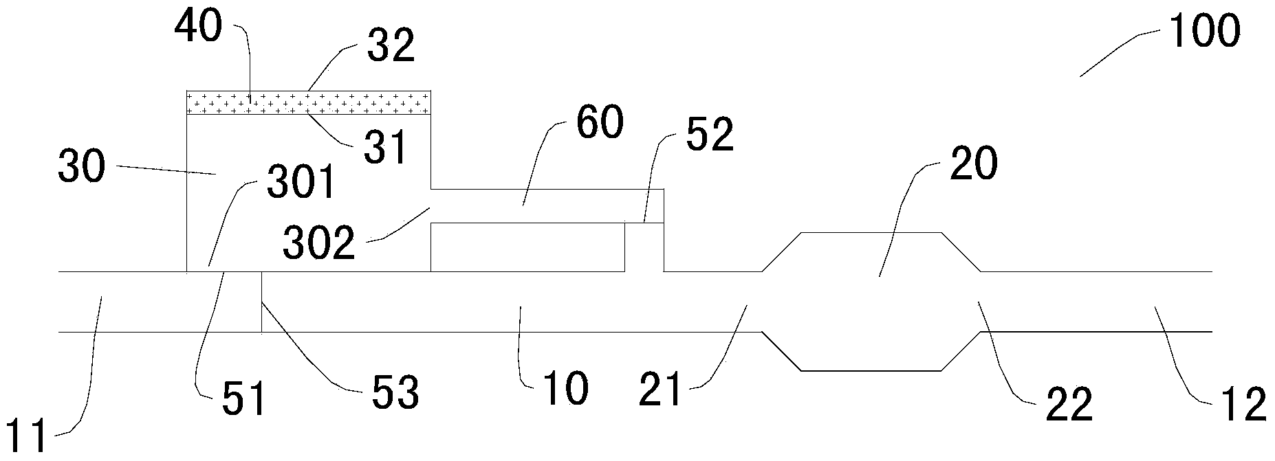
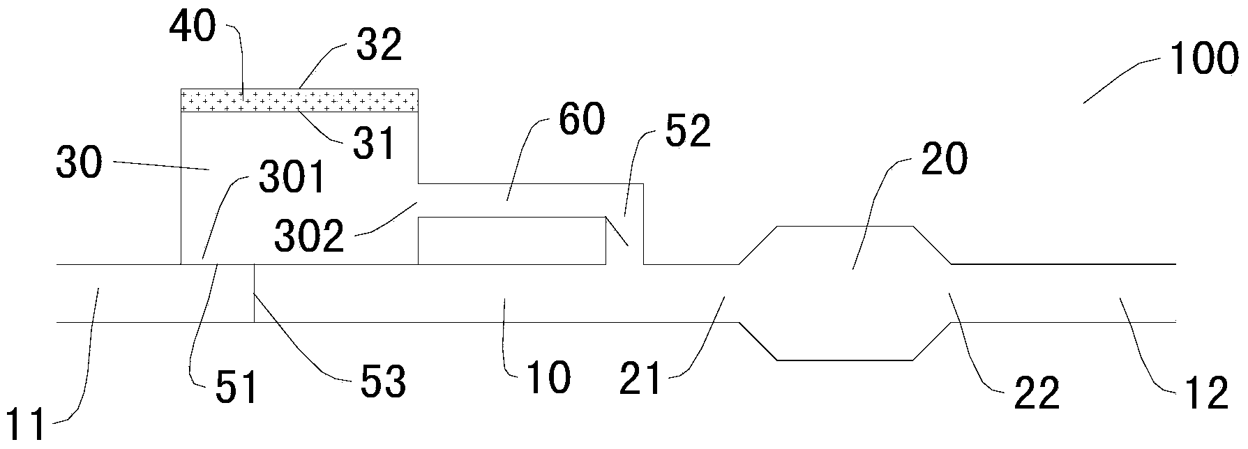
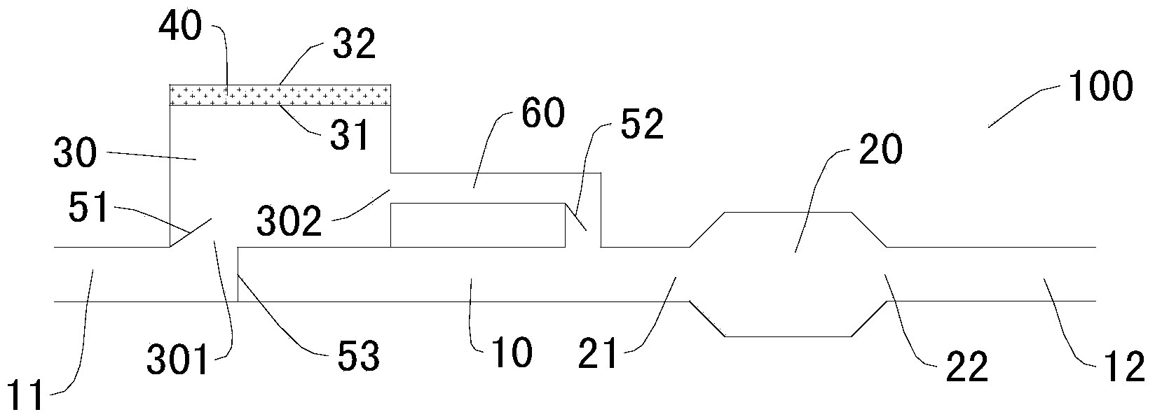
[0036] Embodiments of the present invention are described in detail below, examples of which are shown in the drawings, wherein the same or similar reference numerals designate the same or similar elements or elements having the same or similar functions throughout. The embodiments described below by referring to the figures are exemplary and are intended to explain the present invention and should not be construed as limiting the present invention.

[0037] In describing the present invention, it should be understood that the terms "center", "longitudinal", "transverse", "length", "width", "thickness", "upper", "lower", "front", " Orientation or position indicated by "back", "left", "right", "vertical", "horizontal", "top", "bottom", "inner", "outer", "clockwise", "counterclockwise", etc. The relationship is based on the orientation or positional relationship shown in the drawings, and is only for the convenience of describing the present invention and simplifying the descrip...


PUM


Abstract

The invention discloses an exhaust system applied to a vehicle and the vehicle provided with the exhaust system. The exhaust system applied to the vehicle comprises an exhaust pipe, a catalytic converter, a heat-preserving gas storage tank and a temperature adjustment layer, wherein a gas inlet of the exhaust pipe is connected with an outlet of an exhaust pipeline of an engine of the vehicle; the catalytic converter is arranged on the exhaust pipe and located between the gas inlet of the exhaust pipe and a gas outlet of the exhaust pipe; the heat-preserving gas storage tank is connected with the exhaust pipe to collect waste gas in the exhaust pipe and store the waste gas, and the heat-preserving gas storage tank can selectively supply the stored waste gas to the catalytic converter; the temperature adjustment layer can melt to absorb heat and solidify to release heat and is arranged in the heat-preserving gas storage tank to adjust the temperature of the waste gas in the heat-preserving gas storage tank. According to the exhaust system applied to the vehicle, at the time of cold start of the engine, the ignition of a catalyst is accelerated, and the content of harmful substances in the waste gas of the exhaust system is effectively lowered; the temperature of the waste gas in the heat-preserving gas storage tank can be controlled accurately, and therefore the exhaust system saves more energy and is more efficient.

Description

technical field [0001] The invention relates to the field of vehicle exhaust purification, in particular to an exhaust system for a vehicle and a vehicle with the exhaust system. Background technique [0002] In the related art, in order to accelerate the catalyst light-off and further purify the exhaust gas of the vehicle when the vehicle is cold-started, the following methods are mainly used in the exhaust system of the vehicle to accelerate the catalyst light-off: [0003] The first type is pre-main catalyst or pre-catalyst. This type of method will cause rapid aging of the catalyst due to the high heat load under the high-load operating condition of the engine, and the large exhaust resistance will reduce the power performance of the engine. Therefore, the durability and high temperature resistance of the catalyst are highly required; [0004] The second type, HC collector or electric heating catalyst, adopting this method needs to add some structures in the exhaust pip...

Claims


Application Information

Patent Timeline
Patent Type & Authority Applications(China)
IPC IPC(8): F01N3/20
CPCY02A50/20
Inventor 李东辉刘刚刘亚奇苏艳君关昊
Owner GREAT WALL MOTOR CO LTD
Why Eureka
Try Eureka