
Internal combustion engine energy-saving device

An energy-saving device and internal combustion engine technology, applied in the direction of internal combustion piston engines, combustion engines, mechanical equipment, etc., can solve the problems of reducing the output power of internal combustion engines, complex devices, and prone to failure, so as to increase the amount of generation, stability, and fuel consumption Effect of reducing and preventing knocking phenomenon

Inactive Publication Date: 2014-06-04
徐杰
View PDF5 Cites 2 Cited by
  • Summary
  • Abstract
  • Description
  • Claims
  • Application Information

AI Technical Summary

Problems solved by technology

[0002] There are usually two kinds of energy-saving methods for internal combustion engines in the prior art: 1. reduce the output power of the internal combustion engine, that is, reduce the exhaust volume of the engine, but this cannot meet the working requirements of the internal combustion engine
2. Improve the fuel combustion efficiency of the internal combustion engine, that is, increase the fuel utilization rate, but the device is more complicated, difficult to install, and poor in reliability
At present, the energy-saving devices circulating in the market are roughly divided into the following categories: one is mechanical, such as electronic carburettors, which have high production costs, difficult installation, and are prone to failure and difficult to maintain.
The second is chemical preparations, which have very strict requirements on fuel and combustion, and are not universal
And there will be a lot of dust in the air intake pipe. If you work for a long time, a layer of dust will accumulate on the ozone generator, causing the ozone generator to not work.

Method used


Image

  • Internal combustion engine energy-saving device
  • Internal combustion engine energy-saving device
  • Internal combustion engine energy-saving device

Examples


Embodiment Construction

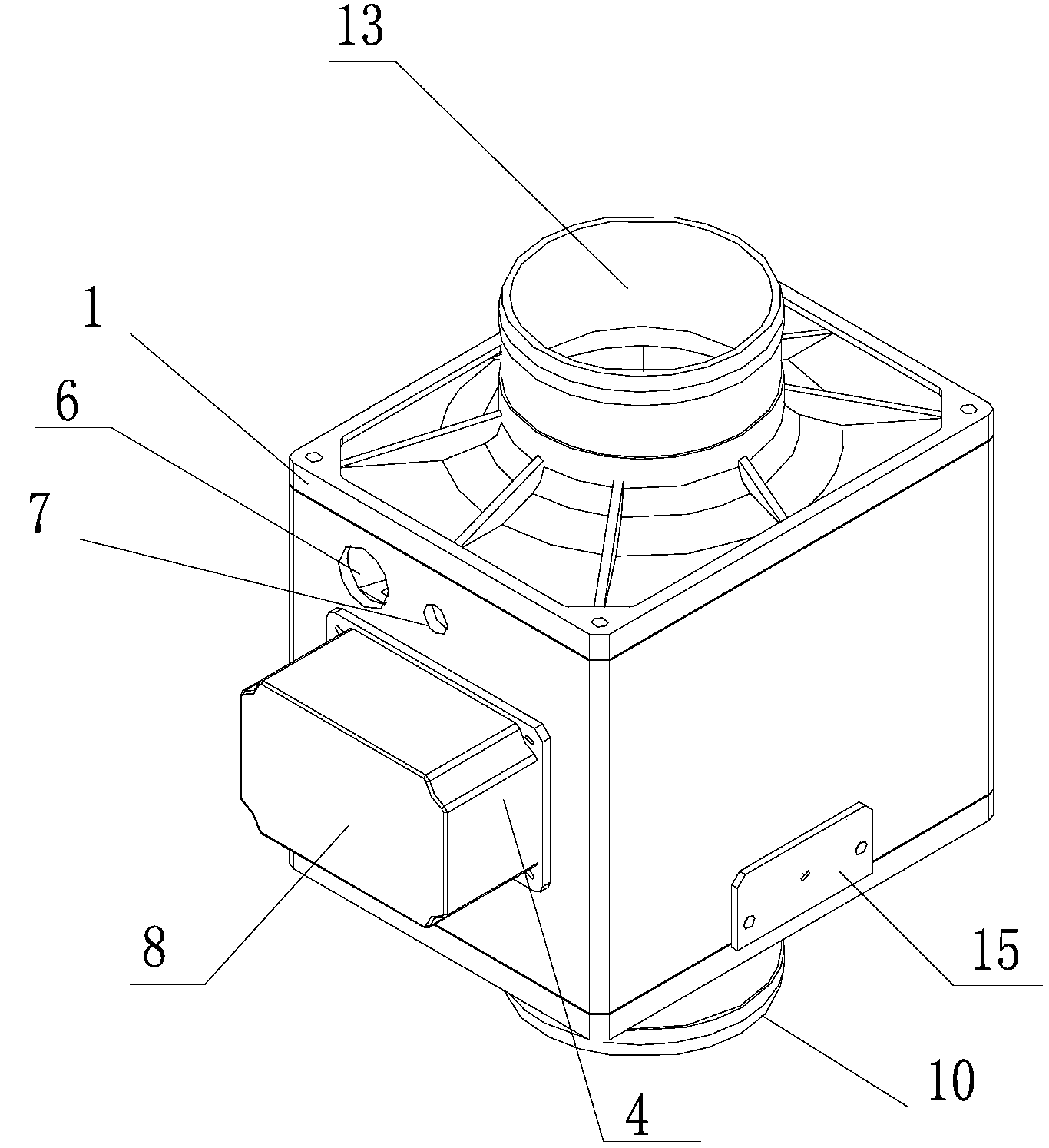
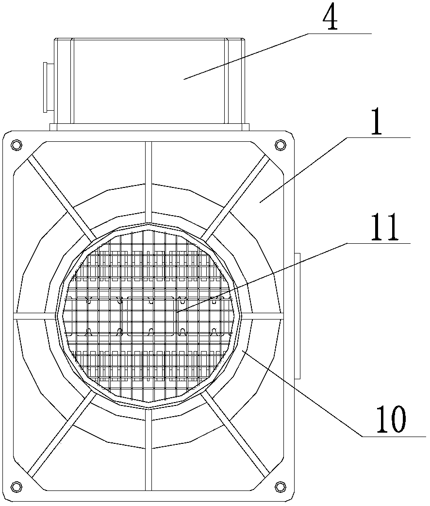
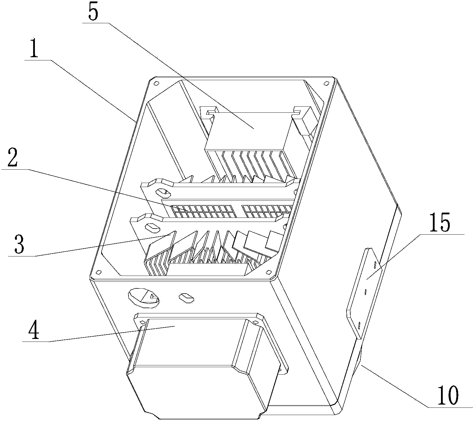
[0019] The energy-saving device for an internal combustion engine of the present invention comprises a housing 1 which is hollow inside. The opposite sides of the housing 1 are provided with an air inlet 13 and an air outlet 10. The air inlet 13 communicates with the intake pipe of the internal combustion engine, and the air outlet 10 communicates with the engine of the internal combustion engine. , the inside of the housing 1 is located between the air inlet 13 and the air outlet 10 and is provided with two opposite heat sinks 3, and the opposite faces of the two heat sinks 3 are provided with an ozone generating sheet 2, and the two heat sinks 3 are opposite to each other. A high-voltage power supply 5 is respectively provided between the surface and the surface of the corresponding housing 1, and the high-voltage power supply 5 is electrically connected to the ozone generator 2. The side of the housing 1 is provided with an intelligent controller 4, and the intelligent contro...


PUM


Abstract

The invention relates to energy-saving devices, in particular to an internal combustion engine energy-saving device. The internal combustion engine energy-saving device comprises a shell with the hollow inside, the two opposite faces of the shell are provided with an air inlet and an air outlet, the air inlet is communicated with an air inlet pipe of an internal combustion engine, the air outlet is communicated with a motor of the internal combustion engine, two cooling fins which are oppositely arranged are arranged between the air inlet and the air outlet inside the shell, and the opposite faces of the two cooling fins are respectively provided with an ozone generating piece. High voltage power sources are arranged between the back-to-back faces of the two cooling fins and the corresponding faces of the shell respectively, the high voltage power sources are electrically connected with an ozone generator, an intelligent controller is arranged on the side face of the shell, and the intelligent controller is electrically connected with the high voltage power sources. Ozone is used for replacing oxygen to be used as combustion-supporting materials, the amount of oxygen is increased, the ozone is used as strong oxidant and can accelerate fuel oxidation reaction, combustion can be conducted better and faster, harmful gas compositions in waste gas are reduced, and the purposes of combustion supporting, pollution reduction and energy saving are achieved.

Description

technical field [0001] The invention relates to an energy-saving device, in particular to an energy-saving device for an internal combustion engine. Background technique [0002] There are usually two methods for energy saving of the internal combustion engine in the prior art: 1. Reduce the output power of the internal combustion engine, that is, reduce the exhaust volume of the engine, but this cannot meet the working requirements of the internal combustion engine. 2. Improve the fuel combustion efficiency of the internal combustion engine, that is, increase the fuel utilization rate, but the device is more complicated, difficult to install, and poor in reliability. Currently, the energy-saving devices circulating in the market are roughly divided into the following categories: First, mechanical devices, such as electronic carburettors, have high production costs, are difficult to install, and are prone to failure and difficult to maintain. The second is chemical preparat...

Claims


Application Information

Patent Timeline
Patent Type & Authority Applications(China)
IPC IPC(8): F02M25/12C01B13/11
CPCY02P20/10Y02T10/12
Inventor 徐杰田文亮
Owner 徐杰
Learn More