Undersea sealing system, tidal power generation unit applying same and application method

A technology of sealing system and generator set, applied in the field of sealing, which can solve the problems of poor sealing performance, low service life of sealing ring, dry friction of sealing ring, etc., so as to increase service life and sealing performance, avoid destructive accidents, and ensure sealing performance effect

Active Publication Date: 2014-06-04
GUODIAN UNITED POWER TECH
View PDF5 Cites 7 Cited by
  • Summary
  • Abstract
  • Description
  • Claims
  • Application Information

AI Technical Summary

Problems solved by technology

[0003] At present, tidal energy generating units are generally arranged at a water depth of 20 meters to 30 meters below sea level, and the dynamic sealing method between the drive shaft of the unit and the engine room mostly adopts a mechanical sealing structure, which uses springs to supplement the elastic force and balance the pressure of seawater. The sealing element is tightly fixed on the groove end face of the inner sealing ring to prevent the axial displacement of the sealing element, so as to ensure the sealing effect of the sealing structure, but this sealing structure has the following disadvantages: (1) Fast wear, the sealing ring (2) The media on both sides of the sealing ring are seawater and lubricating oil, and seawater can easily dilute the lubricating oil film formed on the lip of the sealing ring, resulting in dry friction of the sealing ring, resulting in poor sealing performance; (3) This kind of sealing structure cannot provide condition monitoring, and cannot know in real time whether the drive shaft seal of the tidal energy generating set is intact
[0004] This shows, above-mentioned existing tidal energy generating set transmission shaft and the engine room sealing mode, obviously still have inconvenience and defect, and urgently need to be further improved

Method used


Image

  • Undersea sealing system, tidal power generation unit applying same and application method
  • Undersea sealing system, tidal power generation unit applying same and application method
  • Undersea sealing system, tidal power generation unit applying same and application method

Examples


Embodiment Construction

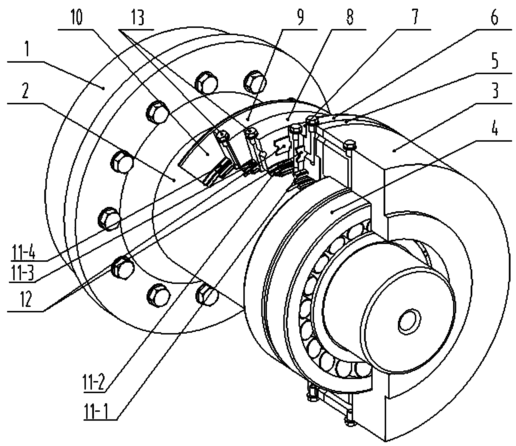
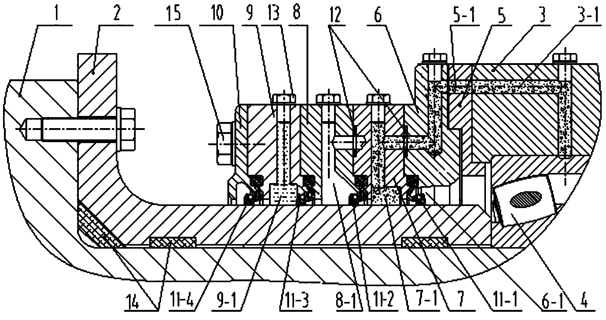
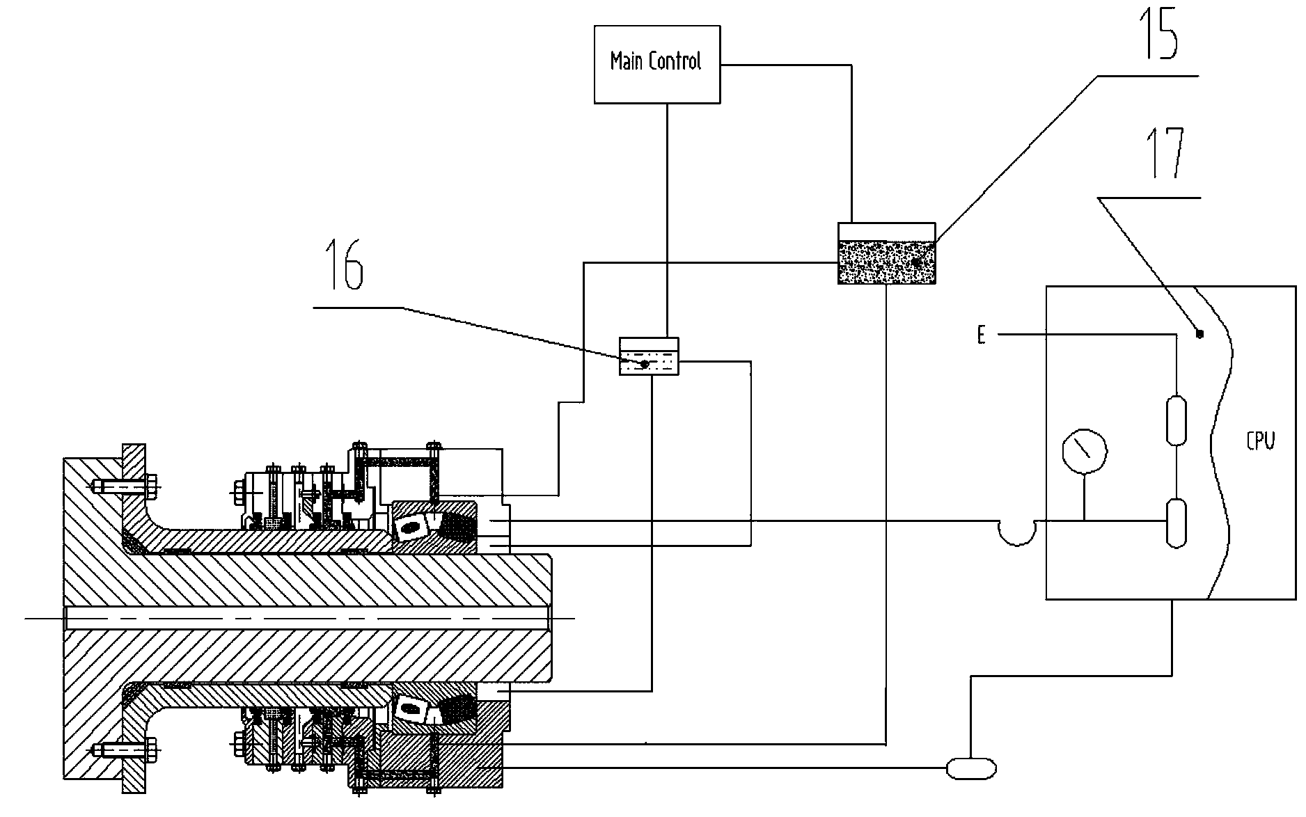
[0039] The invention provides an underwater sealing system, which is used for the sealing connection between the underwater non-rotating parts and the rotating parts. Applying this sealing method to the seawater underwater tidal energy generator set can effectively protect the transmission shaft and the engine room for a long time. Make a seal.

[0040] see figure 1 , figure 2 As shown, the transmission shaft 1 is used as an underwater rotating part, and the shaft sleeve 2 is sleeved on it. In order to strengthen the sealing performance, the inner wall of the shaft sleeve 2 is provided with multiple annular grooves, and a sealing ring 14 is installed in the groove. The underwater sealing system of the present invention includes a dynamic seal and a seal body set on the shaft sleeve 2, the seal body forms a pressure chamber on both sides of the dynamic seal, and the dynamic seal is strengthened by the pressure difference between the pressure chambers on both sides. Sealed co...


PUM


Abstract

The invention discloses an undersea sealing system, a tidal power generation unit applying the same and an application method. The undersea sealing system comprises a movable sealing member and sealing bodies, and the movable sealing member and the sealing bodies sleeve a rotating member. Pressure cavities are formed on two sides of the movable sealing member by the sealing bodies. Sealing connection between the movable sealing member and the rotating member is enhanced through differential pressure between the pressure cavities on the two sides of the movable sealing member. The undersea sealing system is good in sealing performance, safe and reliable, not easy to wear and long in service life. Transmission shafts and cabins of the undersea tidal power generation unit applying the undersea sealing system can be effectively sealed in a long time. Sealing states can be transmitted to an offshore monitoring center through pressure sensors, sealing conditions of the undersea unit can be monitored in real time, and early warning and timely maintenance can be realized.

Description

technical field [0001] The invention relates to the technical field of sealing, in particular to an underwater sealing system, a tidal energy generating set using the same and an application method. Background technique [0002] With the deepening of ocean development activities, tidal power generation technology has been widely used. Among them, the sealing of the tidal energy generating set is a key problem to be solved, especially the dynamic seal between the rotating shaft of the tidal energy generating set and the engine room, the performance of which directly affects whether the tidal energy generating set can work normally, or even It directly affects the safety and life of the unit. [0003] At present, tidal energy generating units are generally arranged at a water depth of 20 meters to 30 meters below sea level, and the dynamic sealing method between the drive shaft of the unit and the engine room mostly adopts a mechanical sealing structure, which uses springs to...

Claims


Application Information

Patent Timeline
Patent Type & Authority Applications(China)
IPC IPC(8): F03B11/00F16J15/16
CPCY02E10/226Y02E10/20
Inventor 胡雪松李明辉王海龙李应昌刘敬波
Owner GUODIAN UNITED POWER TECH
Why Eureka
Try Eureka