Rotating shaft structure and lamp with same

A rotating shaft structure and technology of rotating shaft, applied in the direction of shaft and bearing, pivot shaft, engine lubrication, etc., can solve the problems of easy accumulation of dust on rotating shaft and shaft sleeve, difficult to guarantee the lubrication effect, difficult to add lubricating oil, etc., to achieve easy installation. performance, improved service life, and strong corrosion resistance

Active Publication Date: 2014-06-04
SHENZHEN OCEANS KING LIGHTING ENG CO LTD +1
View PDF6 Cites 3 Cited by
  • Summary
  • Abstract
  • Description
  • Claims
  • Application Information

AI Technical Summary

Problems solved by technology

After long-term use, the positioning pin is easy to fall off, and it is difficult to disassemble the riveting. At the same time, it is necessary to add lubricating oil to the surface of the metal shaft regularly.
However, due to the small gap between the shaft and the shaft sleeve, and the dust is easy to accumulate between the shaft and the shaft sleeve, it is difficult to add lubricating oil and the lubrication effect is difficult to guarantee.

Method used


Image

  • Rotating shaft structure and lamp with same
  • Rotating shaft structure and lamp with same
  • Rotating shaft structure and lamp with same

Examples


Embodiment Construction

[0021] The following will clearly and completely describe the technical solutions in the embodiments of the present invention with reference to the accompanying drawings in the embodiments of the present invention. Obviously, the described embodiments are only some, not all, embodiments of the present invention. Based on the embodiments of the present invention, all other embodiments obtained by persons of ordinary skill in the art without creative efforts fall within the protection scope of the present invention.

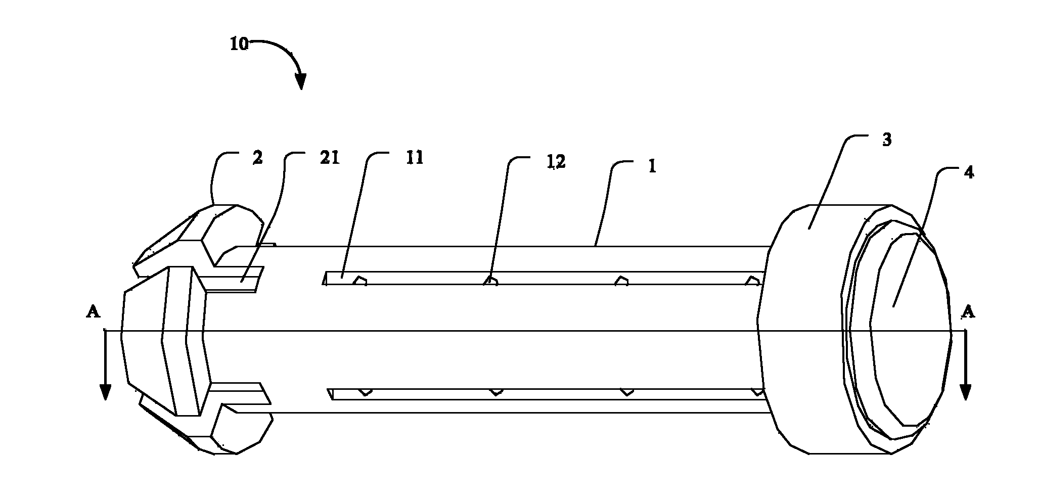
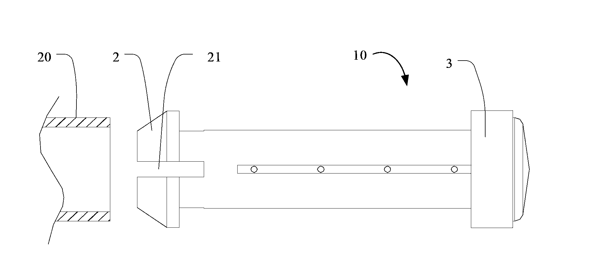
[0022] The embodiment of the present invention provides a lamp. The lamp (not shown) includes a lamp cover (not shown) and a lamp housing (not shown). The lamp cover and the lamp housing are passed through a shaft sleeve 20 and A rotating shaft structure 10 is connected.

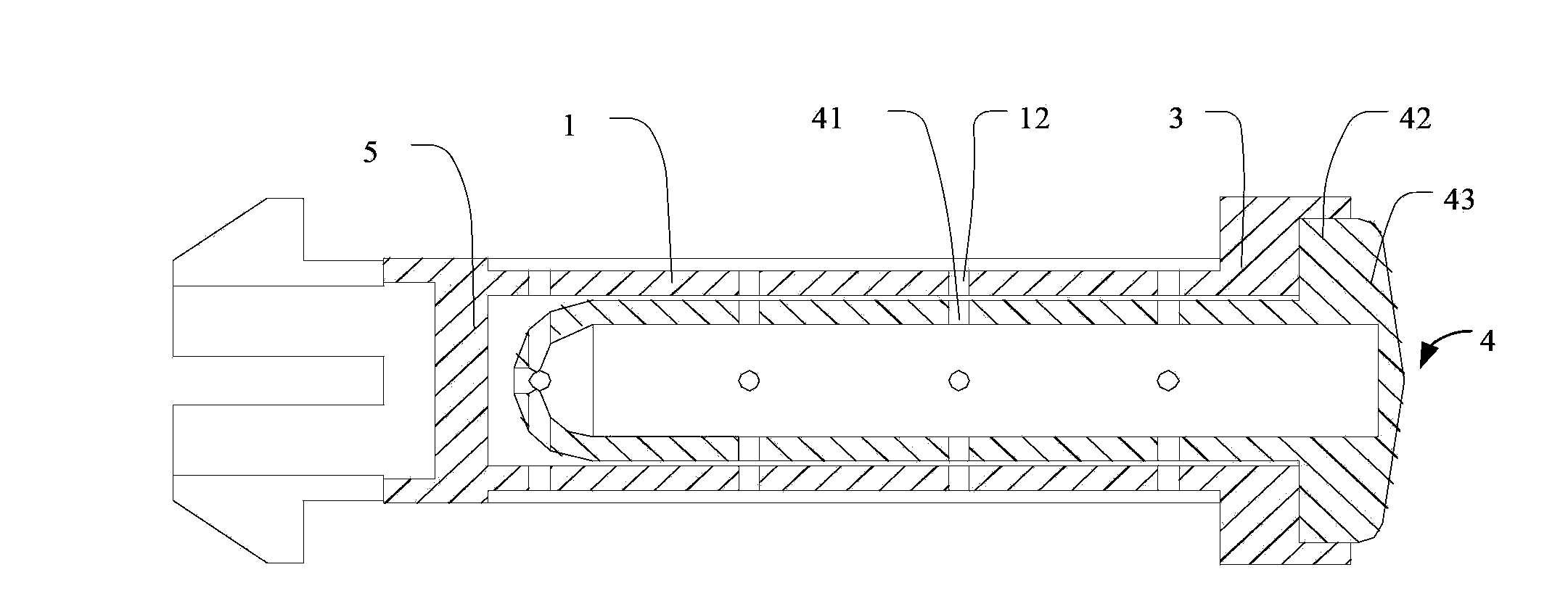
[0023] see figure 1 , is a rotating shaft structure 10 provided in an embodiment of the present invention for assembling the rotating shaft structure 10 and the bushing 20 , the rotating shaft s...


PUM


Abstract

The invention relates to a rotating shaft structure for assembling a rotating shaft and a shaft sleeve. The rotating shaft structure comprises a pipe shaft and a lubricating oil dropper, wherein an annular flange is arranged at a first end part of the pipe shaft, the outer diameter of the annular flange is larger than that of the pipe shaft, a plurality of opening troughs are formed in the end part of the annular flange, the annular flange is made of one of high-strength plastic cement or carbon fiber, a second end part of the pipe shaft is opened and is provided with a limiting flange, the annular flange and the limiting flange are used for limiting the shaft sleeve, the pipe shaft is hollow, and a plurality of first guide holes penetrating through a hollow part of the pipe shaft are formed in the outer wall of the pipe shaft; the lubricating oil dropper is contained in the inner cavity of the pipe shaft, a plurality of second guide holes matched with the first guide holes are formed in the side wall of the lubricating oil dropper, a polymeric membrane layer is paved on the outer wall of the lubricating oil dropper, and lubricating oil permeates to the outer wall of the pipe shaft by virtue of the second guide holes, the polymeric membrane layer and the first guide holes. By utilizing the rotating shaft structure, the installability, corrosion resistance and efficient lubricity of the rotating shaft structure are improved. Besides, the invention further discloses a lamp with the rotating shaft structure.

Description

technical field [0001] The invention relates to the lighting field, in particular to a rotating shaft structure and a lamp with the rotating shaft structure. Background technique [0002] The opening structure of lamps in the prior art all uses a metal rotating shaft, and the rotating shaft is fixed in the shaft sleeve by means of positioning pins or riveting. After long-term use, the positioning pins are easy to fall off, and riveting and disassembly are also difficult. At the same time, lubricating oil must be added to the surface of the metal shaft regularly. However, due to the small gap between the rotating shaft and the shaft sleeve, and the accumulation of dust between the rotating shaft and the shaft sleeve, it is difficult to add lubricating oil and the lubrication effect is difficult to guarantee. Contents of the invention [0003] The technical problem to be solved by the present invention is to provide a rotating shaft structure and a lamp with the rotating sh...

Claims


Application Information

Patent Timeline
Patent Type & Authority Applications(China)
IPC IPC(8): F16C11/00F16N1/00F21V17/10
Inventor 周明杰姜涛
Owner SHENZHEN OCEANS KING LIGHTING ENG CO LTD
Why Eureka
Try Eureka