
Ball valve and control method thereof

A control method and ball valve technology, applied in the field of valve machinery, can solve the problems of poor valve sealing wear resistance, perforation, valve body, valve seat weld impermeability, etc., to reduce gaps, small flow resistance, improve service life and The effect of tightness

Inactive Publication Date: 2014-06-04
JIANG SU YAN DIAN FA MEN CO LTD
View PDF4 Cites 6 Cited by
  • Summary
  • Abstract
  • Description
  • Claims
  • Application Information

AI Technical Summary

Problems solved by technology

[0003] As a control valve for pipeline transportation, due to the solid particles in the medium, the first reason is that the valve seal has poor wear resistance, the sealing surface is easily damaged, and the weld seam of the valve body and seat is impenetrable, resulting in weld failure. perforation

Method used

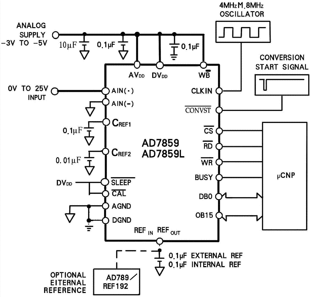
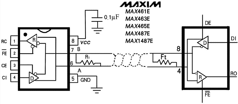
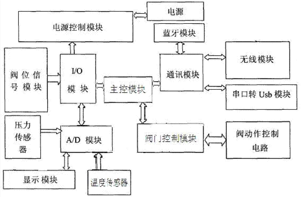

Image

  • Ball valve and control method thereof
  • Ball valve and control method thereof
  • Ball valve and control method thereof

Examples


Embodiment Construction

[0116] The cryogenic ball valve of the present invention includes a valve body, a valve cover, a valve seat assembly, a ball, a valve stem, a spring, a fixed shaft, a long neck bracket, a top bracket, a driving device, and the like. The valve body and the valve cover each have flow passages, and the valve body and the valve cover are connected through gaskets, studs and nuts. The ball is placed in the valve body, and there is a valve seat assembly on both sides of the ball, which are respectively connected to the inside of the valve body and the valve cover. The driving device is connected to the upper part of the valve stem through a key, and the lower end of the valve stem is connected to the ball. The rotation makes the valve stem and the ball rotate around the axis to realize the opening and closing of the valve at 90°.

[0117] The bottom surface of the upper part of the sphere in contact with the valve stem adopts an arc surface, and the two sides are corresponding paral...


PUM


Abstract

The invention discloses a ball valve. The ball valve comprises a valve body, a valve cover, valve seat assemblies, a ball, a valve rod, a spring, a fixed shaft, a long-neck support and a top support and further provided with a driving device. The valve body and the valve cover are respectively provided with a flow channel and connected through a gasket, a stud and a nut; the ball is arranged in the valve body, and the two sides of the ball are respectively provided with one valve seat assembly and connected with the inside of the valve body and the inside of the valve cover respectively; the driving device is connected with the upper portion of the valve rod through a key, the lower end of the valve rod is connected with the ball, and the driving device rotates to make the valve rod and the ball to rotate around the axis so that the valve can be opened or closed by 90 degrees. Corners of an upper seal support, a packing gasket and a packing pressing sleeve are designed into rounded corners, the gap is appropriately increased for inner holes, and the gap is appropriately reduced for outer circles. Roller forming and surface nitriding treatment are adopted for the surface of the valve rod to improve the surface hardness of the valve rod and prevent the surface of the valve rod from straining and galling, mechanical abrasion is reduced, and operation torque of the valve is reduced.

Description

technical field [0001] The invention relates to the technical field of valve machinery, in particular to a ball valve and a control method thereof. Background technique [0002] With the increasing production capacity of petroleum, petrochemical, electric power, metallurgy and other industries, there is an urgent need for a high-performance, high-parameter valve product to replace the original old product to ensure production and improve work efficiency. [0003] As a control valve for pipeline transportation, due to the solid particles in the medium, the first reason is that the valve seal has poor wear resistance, the sealing surface is easily damaged, and the weld seam of the valve body and seat is impenetrable, resulting in weld failure. Seam leakage or perforation. With the continuous improvement of valve technology and the emergence of high-performance materials and automation equipment, old products gradually withdraw from market competitiveness. Contents of the in...

Claims


Application Information

Patent Timeline
IPC IPC(8): F16K5/06F16K31/02F16K37/00
CPCF16K5/06F16K5/0647F16K5/0657F16K27/067F16K37/0083F16K37/0091
Inventor 黄晓峰李昌跃顾世军马正平孙德林刘慎良
Owner JIANG SU YAN DIAN FA MEN CO LTD
Learn More