Expanded connection structure assembly for heat sinks

An expansion joint and heat sink technology, applied in lighting and heating equipment, cooling/heating devices of lighting devices, point light sources, etc., can solve the problems of reduced reliability of screw connections, affecting heat dissipation, and affecting the firmness of installation, etc., to achieve Save manufacturing and use costs, good heat conduction effect, and avoid the effect of heat sink falling off

Inactive Publication Date: 2014-06-04
CHONGQING UNIV
View PDF4 Cites 4 Cited by
  • Summary
  • Abstract
  • Description
  • Claims
  • Application Information

AI Technical Summary

Problems solved by technology

Although LED lights have the above advantages, they will generate a lot of heat during the process of emitting light, and the long-term accumulation of this heat will lead to LED light failure and failure
In order to solve the heat dissipation problem of LED lamps, the LED lamp illuminant is generally installed on the heat dissipation substrate, and the surface of the heat sink is directly attached to the heat dissipation substrate, and the heat is transferred to the heat dissipation substrate through heat conduction; more commonly, the heat sink is used to adhere to the heat dissipation substrate through external force (The heat dissipation of the solar cell panel also adopts this structure or similar structure). Due to the relatively large surface area, the force point is relatively limited, and in order to prevent damage to the LED lamp, it is impossible to apply a large bonding force, so it cannot be tightly bonded. In the prior art, for rectangular heat sinks, screw connection is generally used for bonding, but due to structural limitations, in fact, only two diagonal screws are installed and fastened, which not only complicates the installation structure , the heat sink and the heat dissipation substrate cannot be tightly bonded, and the heat sink will be deformed due to the increase in temperature during use, and the separation of the two surfaces will affect heat conduction and heat dissipation; moreover, frequent alternation of cold and heat will cause The reliability of the screw connection is reduced, which affects the firmness of the installation and thus affects the heat dissipation; even if a thermal conductive adhesive is added between the two surfaces, the heat conduction effect will still be reduced after long-term use

Method used


Image

  • Expanded connection structure assembly for heat sinks
  • Expanded connection structure assembly for heat sinks
  • Expanded connection structure assembly for heat sinks

Examples


Embodiment Construction

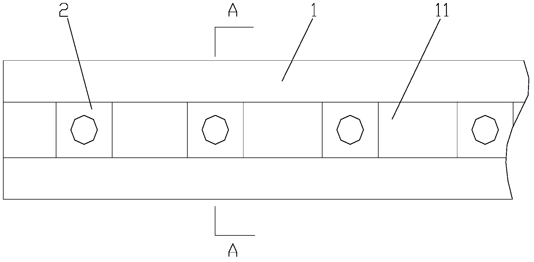
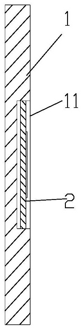
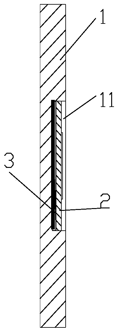
[0022] figure 1 It is a schematic diagram of the structure of the present invention, figure 2 for figure 1 A cross-sectional view along the A-A direction (there is a gap between the bottom surface of the heat sink and the bottom of the expansion groove), as shown in the figure: this embodiment takes an LED lamp as an example, of course, it is also applicable to solar cells and other equipment with heat dissipation requirements; the heat sink The expansion joint structure assembly includes a heat dissipation base plate 1 and a heat sink 2. The surface of the heat dissipation base plate 1 is provided with an expansion joint groove 11. In the expansion slot 11; the heat dissipation substrate is generally made of materials with good thermal conductivity, such as aluminum or copper, and more and transparent heat dissipation fins are set if necessary, which will not be repeated here; The interference fit is located on the side, and there is no need to apply a large pressure on th...


PUM


Abstract

The invention discloses an expanded connection structure assembly for heat sinks. The expanded connection structure assembly for the heat sinks comprises a heat dissipation substrate and the heat sinks. The surface of the heat dissipation substrate is provided with an expanded connection groove. The heat sinks are fixedly arranged in the expanded connection groove through the mode that the side faces of the heat sinks are in interference fit with the side walls of the expanded connection groove. Due to interference fit, the heat sinks are connected and attached closely to the expanded connection groove, and the heat conduction effect is good. After detection, it shows that heat dissipation efficiency is improved by over 20 percent compared with existing connecting modes of screws and the like. In addition, according to the installation mode, the stressed points are located on the side edges of the heat sinks, so that the performance of heating equipment on the heat sinks is prevented from being affected by large interference fit force. Because of the installation in an interference fit mode, the heat sinks produce larger expansion joint force due to the effect of thermal expansion and cold contraction after being heated, so that the installation is firmer; after cooling, the heat sinks can still keep an original interference installation effect, so that the heat sinks are prevented from falling off, and the reliability of the installation is guaranteed. Meanwhile, according to the structure, an existing rivet and screw connection structure is omitted. The expanded connection structure assembly for the heat sinks can be installed without the aid of other parts and is simple in structure, easy to install and capable of saving manufacturing cost and usage cost.

Description

technical field [0001] The invention relates to an installation structure suitable for heating equipment such as solar cells and LED lamps, in particular to a heat dissipation component installation assembly with better heat dissipation effect. Background technique [0002] In the energy conversion in daily life and industrial production, there are many heating devices involved, and heat dissipation is bound to be involved; for example, solar cells, LEDs, etc., will conduct heat to the heat sink through the transition piece; transition The parts may be called connection plates or heat sinks, which are collectively referred to as heat sinks in the present invention. [0003] Taking LED lights as an example, LED lights have the advantages of low voltage, low energy consumption, no pollution to the environment, strong adaptability, long service life and short response time, and are widely used in various fields. Although the LED lamp has the above advantages, a large amount of...

Claims


Application Information

Patent Timeline
IPC IPC(8): F21V29/00H01L31/052F21Y101/02F21V29/51F21V29/70
CPCY02E10/50
Inventor 何川郑文彪
Owner CHONGQING UNIV
Why Eureka
Try Eureka