Modulation and demodulation method of distributed optical fiber sensor based on multi-domain hybrid multiplexing

A distributed optical fiber, modulation and demodulation technology, applied in the direction of using optical devices to transmit sensing components, etc., can solve the problem that the spectrum analyzer cannot provide an external control interface, time-division signal demodulation cannot achieve real-time performance, and TDM time-division multiplexing cannot be performed and other issues, to achieve strong scalability, facilitate large-scale application promotion, improve accuracy or light source bandwidth

Active Publication Date: 2016-06-29
HUAZHONG UNIV OF SCI & TECH
View PDF9 Cites 0 Cited by
  • Summary
  • Abstract
  • Description
  • Claims
  • Application Information

AI Technical Summary

Problems solved by technology

[0003] U.S. Naval Research Laboratory T.A.Berkoff et al. in the paper "HYBRIDTIMEANDWAVELENGTHDIVISIONMULTIPLEXEDFIBERBRAGGGRATINGSENSORRAY" Proc.SPIE2444, SmartStructuresandMaterials1995:SmartSensing, Processing, andInstrumentation, 288 (April20, 1995), but the concept of wave division multiplexing, 4" proposed: 10.1117 / 12. Its time-division signal demodulation cannot achieve real-time performance, and the demodulation accuracy is too low to make frequency division multiplexing impossible
[0004] The application number is 201110420315.8, and the patent application titled "quasi-distributed sensor based on microstructure fiber Fabry-Perot resonator" proposes wavelength division and frequency division multiplexing, which uses a spectrum analyzer, which is expensive and can only To achieve two-dimensional multiplexing, due to the long demodulation cycle of the spectrum analyzer, and the spectrum analyzer cannot provide an external control interface, TDM (time division multiplexing) multiplexing cannot be performed

Method used


Image

  • Modulation and demodulation method of distributed optical fiber sensor based on multi-domain hybrid multiplexing
  • Modulation and demodulation method of distributed optical fiber sensor based on multi-domain hybrid multiplexing
  • Modulation and demodulation method of distributed optical fiber sensor based on multi-domain hybrid multiplexing

Examples


Embodiment Construction

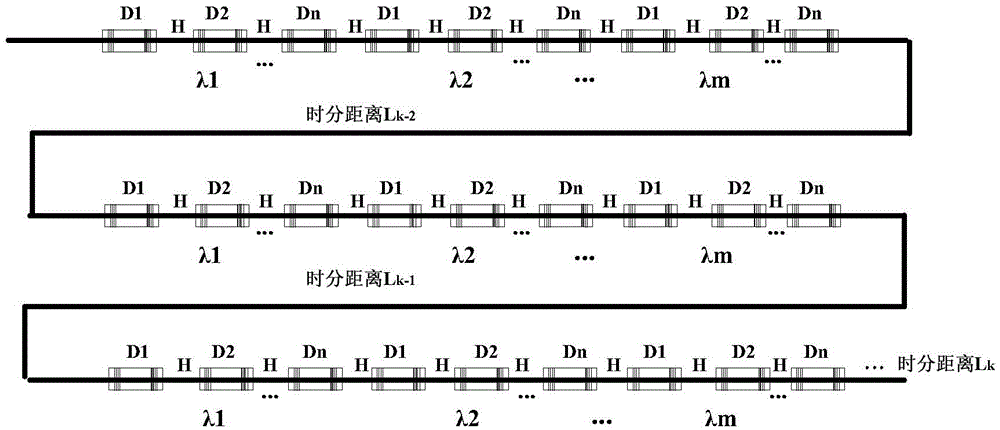
[0032] Aiming at the capacity limitation of the existing two-dimensional multiplexing technology, the present invention proposes three-dimensional multiplexing in time domain, wave domain and frequency domain, and aims at the conflict between real-time demodulation in time domain and long demodulation cycle in wave domain and frequency domain, and designs a Multi-domain optical fiber sensing and its demodulation system software and hardware, optical fiber sensing unit and algorithm can greatly improve the multiplexing capacity and realize single-fiber large-scale sensing multiplexing.

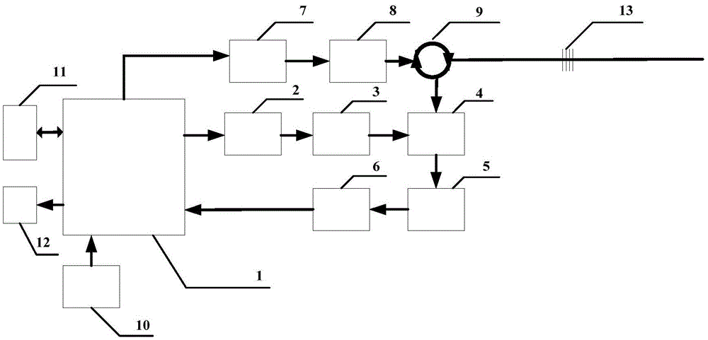
[0033] A multi-domain hybrid multiplexing distributed optical fiber sensing and demodulation device, which consists of a system on chip (SOC), a light source module, an optical fiber sensing unit, a filter control module, a data acquisition module, a data storage module and a data transmission module constitute.

[0034] Described system on chip SOC is the chip that ARM processor and FPGA (Fiel...


PUM


Abstract

The invention relates to a distributed optic fiber sensor based on a multi-domain mixed and multiplex mode and a modulation and demodulation method of the distributed optic fiber sensor. The optic fiber sensor comprises a data processing and controlling device (1), a light source module, an optical fiber sensing unit (13), a filter (4), a filter controlling module, a data collecting module and a light circulator (9). The data processing and controlling device (1) is respectively connected with the light source module, the filter controlling module and the data collecting module, the light circulator (9) is respectively connected with the light source module, the optical fiber sensing unit (13) and the filter (4), the filter controlling module is connected between the data processing and controlling device (1) and the filter (4), and the output end of the filter (4) is further connected with the input end of the data processing and controlling device (1) through the data collecting module. The distributed optic fiber sensor based on the multi-domain mixed and multiplex mode has the advantages of being large in capacity, low in cost, high in modulation and demodulation speed, compact in structure and the like and is suitable for large-scale and distributed sensing multiplexing.

Description

technical field [0001] The invention relates to the technical field of optical fiber sensing, and realizes large-capacity optical fiber sensing by expanding the multi-domain characteristics of optical signals in the optical fiber, and specially designs an embedded demodulation system for the sensing method. Background technique [0002] Optical fiber sensing is widely used in the monitoring of geological disasters, oceans, and large structures. Its anti-electromagnetic properties, compact structure, high sensing accuracy, and high scalability have attracted more and more attention. Because the demodulation system of fiber optic sensing is relatively expensive, increasing the number of single-fiber multiplexing can significantly reduce the demodulation cost of a single sensing node and expand its application field. [0003] U.S. Naval Research Laboratory T.A.Berkoff et al. in the paper "HYBRIDTIMEANDWAVELENGTHDIVISIONMULTIPLEXEDFIBERBRAGGGRATINGSENSORRAY" Proc.SPIE2444, Smart...

Claims


Application Information

Patent Timeline
Patent Type & Authority Patents(China)
IPC IPC(8): G01D5/36
Inventor 刘德明程建伟孙琪真李晓磊艾凡
Owner HUAZHONG UNIV OF SCI & TECH
Why Eureka
Try Eureka