Overhead-type excitation displacement velocity force value relation curve detection equipment

A relationship curve, testing equipment technology, applied in the direction of measuring device, mechanical component testing, machine/structural component testing, etc., can solve problems such as failure of testing results, high-frequency vibration of equipment, affecting testing accuracy, etc., and achieve accurate testing data. Reliable, vibration and noise elimination, good flexibility in use

Active Publication Date: 2014-06-04
宁波互生元机电科技有限公司
View PDF5 Cites 4 Cited by
  • Summary
  • Abstract
  • Description
  • Claims
  • Application Information

AI Technical Summary

Problems solved by technology

[0004] 1. During the inspection process of the lower-mounted mechanism, the piston rod at the upper end of the inspected part, especially the hydraulic damping part, is fixed, while the main cylinder needs to move up and down, which causes the oil in the cylinder to slosh violently, and oil in the cavity appears. The saponification and foaming of the liquid may even cause no oil in the test chamber, which will invalidate the test results or cause large deviations in the test data
[0005] 2. There are many factors such as the moment of inertia generated by the crank mechanism, the self-weight of the worktable, the self-weight of the fixture, and the self-weight of the inspected part in the bottom-mounted structure, which causes the equipment to generate large inertia and large energy consumption, making the movement frequency and efficiency of the equipment extremely low
[0006] 3. For the crank mechanism with a bottom-mounted structure, there are connecting rods and eccentric blocks that cause centrifugal force during operation because the center of gravity deviates from the center of rotation of the main shaft. According to the formula, centrifugal force F=0.00112GRn 2 , is with the spindle speed n 2 Increase, so that the device will produce extremely high-frequency vibration and large-scale low-frequency shaking
Make it difficult for the equipment to meet the detection requirements of high operating frequency
[0007] 4. Due to the moment of inertia generated by the up-and-down movement of the undermounted crank mechanism during the detection process, the transmission chain stalls to a certain extent, causing the meshing surface of the transmission chain to change at the critical point of the acceleration section and deceleration section of the crank's sinusoidal motion, resulting in The collision of the meshing surface reduces the service life of the equipment and the detection accuracy of the equipment
[0008] 5. The bottom-mounted crank mechanism mostly adopts fixed eccentricity or manual adjustment of eccentricity; the former is only suitable for the test of one specification product, and the equipment cost and use cost are relatively high; while the latter requires the equipment to be stopped. Manual adjustments, resulting in lower working efficiency of the equipment
The low accuracy of manual adjustment affects the test accuracy, and also affects the safety and handling of the equipment due to its institutional limitations
[0009] As a result of the above defects, the bottom-mounted vibration-exciting displacement-velocity-force relationship curve detection equipment can only lower the center of gravity and operating speed as much as possible to ensure the stability of the equipment, and once the crank mechanism is set as the top-mounted type, the noise and vibration of the equipment will None of them can meet the requirements of the test, which is why there is no top-mounted test device at present

Method used


Image

  • Overhead-type excitation displacement velocity force value relation curve detection equipment
  • Overhead-type excitation displacement velocity force value relation curve detection equipment
  • Overhead-type excitation displacement velocity force value relation curve detection equipment

Examples


Embodiment Construction

[0027] The present invention will be further described below in conjunction with the accompanying drawings and specific embodiments.

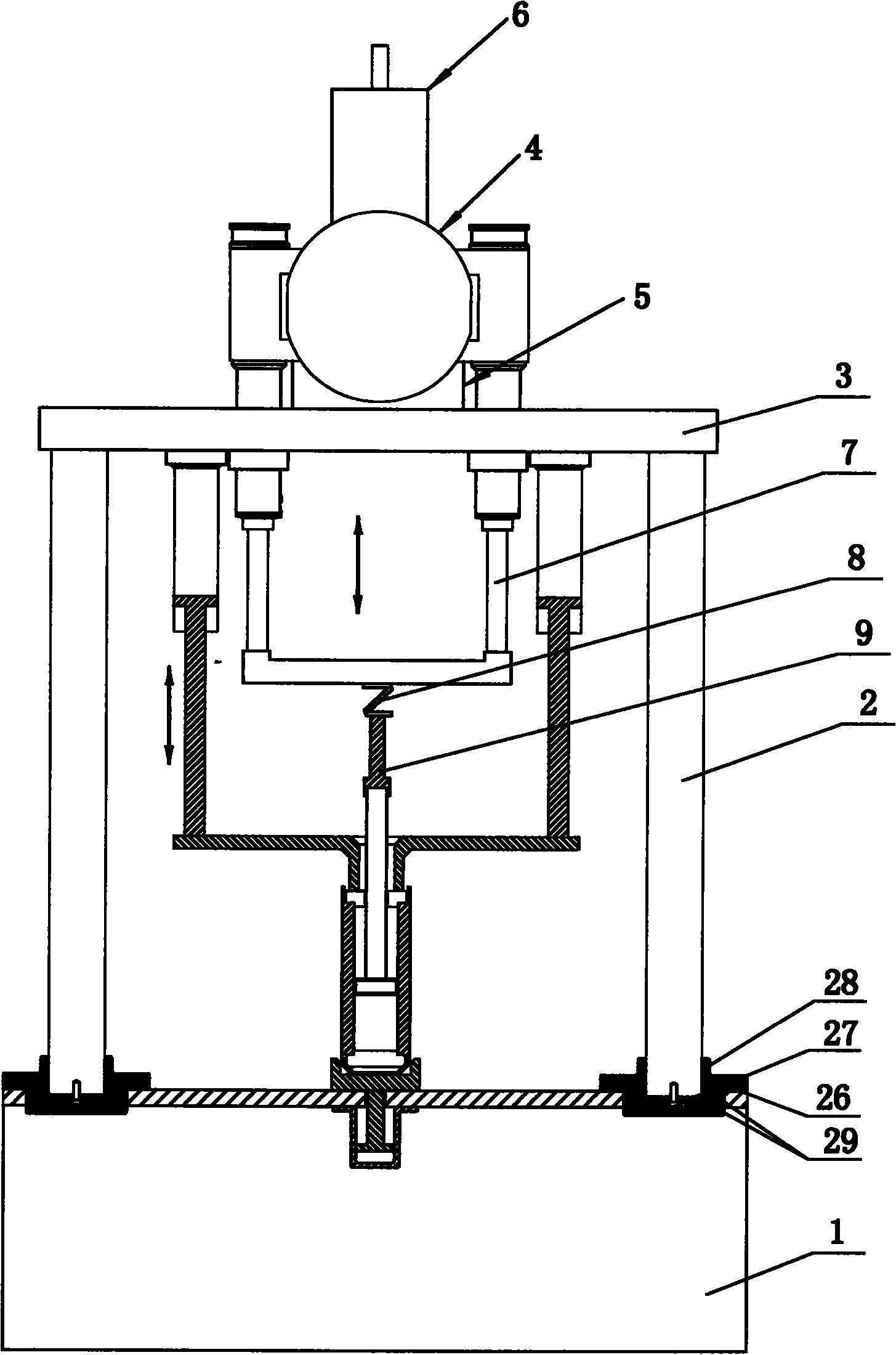
[0028] Such as figure 1 Shown, a kind of upper setting excitation type displacement velocity force value relation curve detection equipment, it comprises base 1, column 2, base plate 3 and crank mechanism 4 (certainly also includes other components, but because it does not involve the invention of the present invention Invention point, so do not go into details here), described column 2 is at least two (this example is four, also can be two, three or five etc.), one end of described column 2 is all connected with The base 1 is connected, and the other ends of the columns 2 are connected to the base plate 3, and the columns 2 are parallel to each other. It also includes a concentric shaft angle difference adjustment mechanism 5 and an anti-backlash mechanism 6. The base plate 3 is slidingly connected with a test The shaft 7 is generally provide...


PUM


Abstract

Overhead-type excitation displacement velocity force value relation curve detection equipment comprises a base (1), a stand column (2), a base plate (3) and a crank mechanism (4) and further comprises a concentric shaft rotation angle difference adjustment mechanism (5) and a gap eliminating mechanism (6), wherein the base plate (3) is connected with a test shaft (7) in a sliding mode, the lower end of the test shaft (7) is connected with a force sensor (8) and an upper clamp (9), the crank mechanism (4), the concentric shaft rotation angle difference adjustment mechanism (5) and the gap eliminating mechanism (6) are all connected to the base plate (3), the gap eliminating mechanism (6) is connected with the crank mechanism (4) which is in transmission connection with the test shaft (7), the crank mechanism (4) comprises an automatic counter weight assembly, and the concentric shaft rotation angle difference adjustment mechanism (5) is connected with the automatic counter weight assembly. Compared with the prior art, the equipment has the advantages that the crank mechanism is in the overhead type, the angle difference can be adjusted in real time, detection efficiency is high, detection precision is good and use flexibility is good.

Description

technical field [0001] The invention relates to a device for detecting the relationship curve of displacement, velocity, and force value of an upper vibration excitation type. Background technique [0002] At present, the detection process of displacement, velocity and force value relationship curve is hydraulic damping parts, rubber elastic parts, springs and parts with creep characteristics, which is an important part of parts manufacturing and testing. The quality of the displacement, velocity and force value relationship curve is directly related to the quality of the above-mentioned inspected parts, and provides a reliable basis for the final application of the product. [0003] The detection devices such as hydraulic damping parts in the prior art all adopt the crank mechanism of the lower type. Through the active force, the crank connecting rod is driven by the eccentric block to make the worktable reciprocate linearly up and down in the sliding sleeve. When in use, t...

Claims


Application Information

Patent Timeline
Patent Type & Authority Applications(China)
IPC IPC(8): G01M17/04G01M13/00
Inventor 娄永标娄永旵
Owner 宁波互生元机电科技有限公司
Why Eureka
Try Eureka