

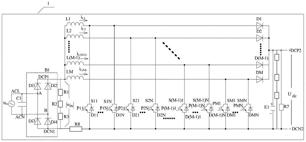
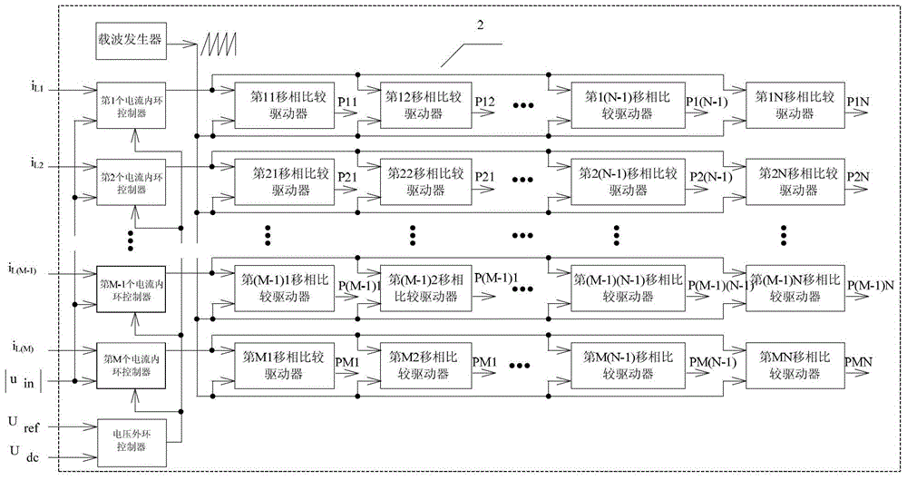
A Composite Power Factor Correction Circuit
A power factor correction and power circuit technology, applied in the direction of output power conversion devices, electrical components, high-efficiency power electronic conversion, etc., can solve the problems of high cost, power device selection and installation difficulties, etc., to reduce the overall cost and benefit Effect of miniaturization design and multiplication of ripple frequency
- Summary
- Abstract
- Description
- Claims
- Application Information
AI Technical Summary
Problems solved by technology
Method used
Image

Examples
Embodiment Construction
[0029] The implementation of the present invention will be illustrated by specific specific examples below, and those skilled in the art can easily understand other advantages and effects of the present invention from the contents disclosed in this specification.
[0030] see figure 1 . It should be noted that the structures, proportions, sizes, etc. shown in the drawings attached to this specification are only used to match the content disclosed in the specification, for those who are familiar with this technology to understand and read, and are not used to limit the implementation of the present invention. Limiting conditions, so there is no technical substantive meaning, any modification of structure, change of proportional relationship or adjustment of size, without affecting the effect and purpose of the present invention, should still fall within the scope of the present invention. The disclosed technical content must be within the scope covered. At the same time, term...
PUM
 Abstract
Description
Claims
Application Information