Laminate body, cross-linked product, and molded member

一种层叠体、体层的技术,应用在管状物品、分层产品、车辆部件等方向,能够解决层叠体可靠性受损等问题,达到层间粘接性优异的效果

Active Publication Date: 2014-06-04
DENKA CO LTD
View PDF8 Cites 6 Cited by
  • Summary
  • Abstract
  • Description
  • Claims
  • Application Information

AI Technical Summary

Problems solved by technology

This is because when the interlayer adhesive strength is low, the reliability of the laminate will be impaired

Method used


Image

  • Laminate body, cross-linked product, and molded member
  • Laminate body, cross-linked product, and molded member
  • Laminate body, cross-linked product, and molded member

Examples


no. 1 approach )

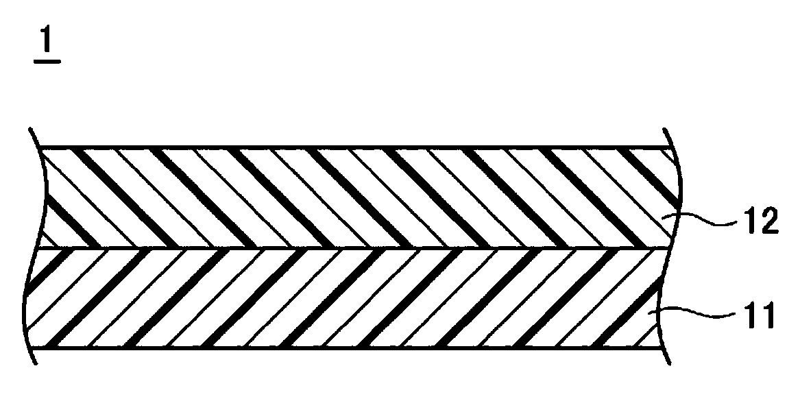
[0031] First, the laminated body of the first embodiment of the present invention will be described. figure 1 It is a cross-sectional view showing a configuration example of the laminated body of the present embodiment. Such as figure 1 As shown, the laminated body 1 of the present embodiment has a structure in which an acrylic elastomer layer 11 and a fluoroelastomer layer 12 are laminated.

[0032] It should be noted, figure 1 shows a laminate of a structure in which an acrylic elastomer layer 11 and a fluoroelastomer layer 12 are laminated one each, but the present invention is not limited thereto, and one or more acrylic elastomer layers may be used. The elastomer layer 11 is laminated with one or more fluoroelastomer layers 12 to form a laminate 1 . At this time, the acrylic elastomer layers 11 and the fluoroelastomer layers 12 are alternately laminated.

[0033] In addition, the laminate 1 of the present embodiment may include layers other than the acrylic elastom...

no. 2 approach )

[0093] Next, the cross-linked product according to the second embodiment of the present invention will be described. The cross-linked product of the present embodiment is obtained by cross-linking the laminate 1 of the first embodiment described above. Preferably, the acrylic elastomer layer 11 and the fluorine-based elastomer layer 12 are crosslinked at the interface between the elastomers, so that they are crosslinked and bonded. Therefore, in the present embodiment, crosslinking is performed in a state where these layers are stacked to form a crosslinked product. Thereby, a laminated body with stronger interlayer adhesive force can be obtained.

[0094] The crosslinking method at this time is not particularly limited, and common crosslinking methods such as press crosslinking, steam crosslinking, and electron beam crosslinking can be used. In addition, the crosslinking temperature and crosslinking time can be appropriately set according to the formulation of each elastome...

no. 3 approach )

[0098] Next, a molding member according to a third embodiment of the present invention will be described. The molded member of this embodiment is, for example, a sealing member such as a rubber hose, a gasket, or a seal, or an anti-vibration rubber member, and is formed of the laminated body of the first embodiment or the cross-linked product of the second embodiment.

[0099]Examples of rubber hoses include transmission oil cooler hoses, engine oil cooler hoses, air duct hoses, turbo intercooler hoses, hot air hoses, radiator hoses, etc. for automobiles, construction machinery, and hydraulic equipment. Engine hoses, power steering hoses, fuel system hoses, exhaust system hoses, etc. As a configuration of these rubber hoses, reinforcing fibers or steel wires may be provided in the middle of the hose or in the outermost layer of the rubber hose as is usually done.

[0100] In addition, examples of sealing components include engine cover gaskets, oil pan gaskets, oil seals, lip...


PUM


Abstract

Provided are a laminate body having excellent interlayer adhesion, a cross-linked product, and a molded member. An acrylic-based elastomer layer (11) is formed by an acrylic-based elastomer composition containing 1-5 parts by mass of an onium salt and 1-8 parts by mass of a polyol compound with respect to 100 parts by mass of the acrylic-based elastomer, and a fluorine-based elastomer layer (12) is formed by a fluorine-based elastomer composition containing a polyol cross-linking agent. The acrylic-based elastomer layer (11) and the fluorine-based elastomer layer (12) are laminated to obtain a laminate body (1). The laminate body (1) is cross-linked to obtain a cross-linked product and a molded member.

Description

technical field [0001] The present invention relates to a laminate, a cross-linked product, and a molded member using an elastomer. More specifically, it relates to a laminate, a crosslinked product, and a molded member of an acrylic elastomer and a fluoroelastomer. Background technique [0002] Acrylic elastomers and their cross-linked products are used as materials for hose members, sealing members, and anti-vibration rubber members in the engine room of automobiles due to their excellent physical properties such as heat aging resistance, oil resistance, mechanical properties, and compression set properties. And widely used. In addition, in recent years, these automotive members have been required to have materials more excellent in heat aging resistance due to the influence of exhaust gas countermeasures, higher engine output, and the like. [0003] As a method of improving the heat aging resistance and improving the reliability of rubber parts, for example, a method of...

Claims


Application Information

Patent Timeline
Patent Type & Authority Applications(China)
IPC IPC(8): B32B25/00C08K5/13C08K5/19C08K5/50C08L33/14F16F1/36F16J15/10F16L11/04
CPCB32B27/18B32B27/304B32B25/042B32B25/14B32B1/08F16L11/04B32B27/308C08L33/068B32B27/26B32B27/322C08L2203/16B32B2250/02C08L2312/00B32B2250/24B32B2250/248B32B27/08B32B2597/00B32B2307/306B32B2307/56B32B2581/00B32B2605/08Y10T428/1393Y10T428/3154Y10T428/1352Y10T428/1386C08L71/02
Inventor 河崎孝史萩原尚吾宫内俊明
Owner DENKA CO LTD
Why Eureka
Try Eureka