Riveting and positioning fixture, PCB riveting method, manufacturing method for PCB and PCB

A positioning fixture and riveting technology, used in manufacturing tools, printed circuit manufacturing, workpiece clamping devices, etc., can solve the problems of high resin fluidity and pulling force, unable to meet product requirements, and chaotic production management, so as to improve quality, The effect of reducing product scrap and simplifying production management

Inactive Publication Date: 2014-06-11
PEKING UNIV FOUNDER GRP CO LTD +1
View PDF7 Cites 20 Cited by
  • Summary
  • Abstract
  • Description
  • Claims
  • Application Information

AI Technical Summary

Problems solved by technology

[0003] However, the traditional riveting process is affected by the riveting method and the stress problem during the riveting process, which often leads to problems such as misalignment and loose riveting, which eventually lead to the scrapping of the board due to misalignment.
At the same time, the traditional positioning fixtures are made separately according to each model, the production management is chaotic and the production efficiency is low
[0004] In the traditional prepreg riveting process, when multiple high-resin-content prepregs are pressed together with a large-thickness core board, the pulling force due to the fluidity of the resin is very large, and it is prone to misalignment and scrapped
Traditional riveting design will not meet product requirements

Method used


Image

  • Riveting and positioning fixture, PCB riveting method, manufacturing method for PCB and PCB
  • Riveting and positioning fixture, PCB riveting method, manufacturing method for PCB and PCB
  • Riveting and positioning fixture, PCB riveting method, manufacturing method for PCB and PCB

Examples


Embodiment Construction

[0059] In order to understand the above-mentioned purpose, features and advantages of the present invention more clearly, the present invention will be further described in detail below in conjunction with the accompanying drawings and specific embodiments.

[0060] In the following description, many specific details are set forth in order to fully understand the present invention, however, the present invention can also be implemented in other ways than described here, therefore, the present invention is not limited to the specific embodiments disclosed below .

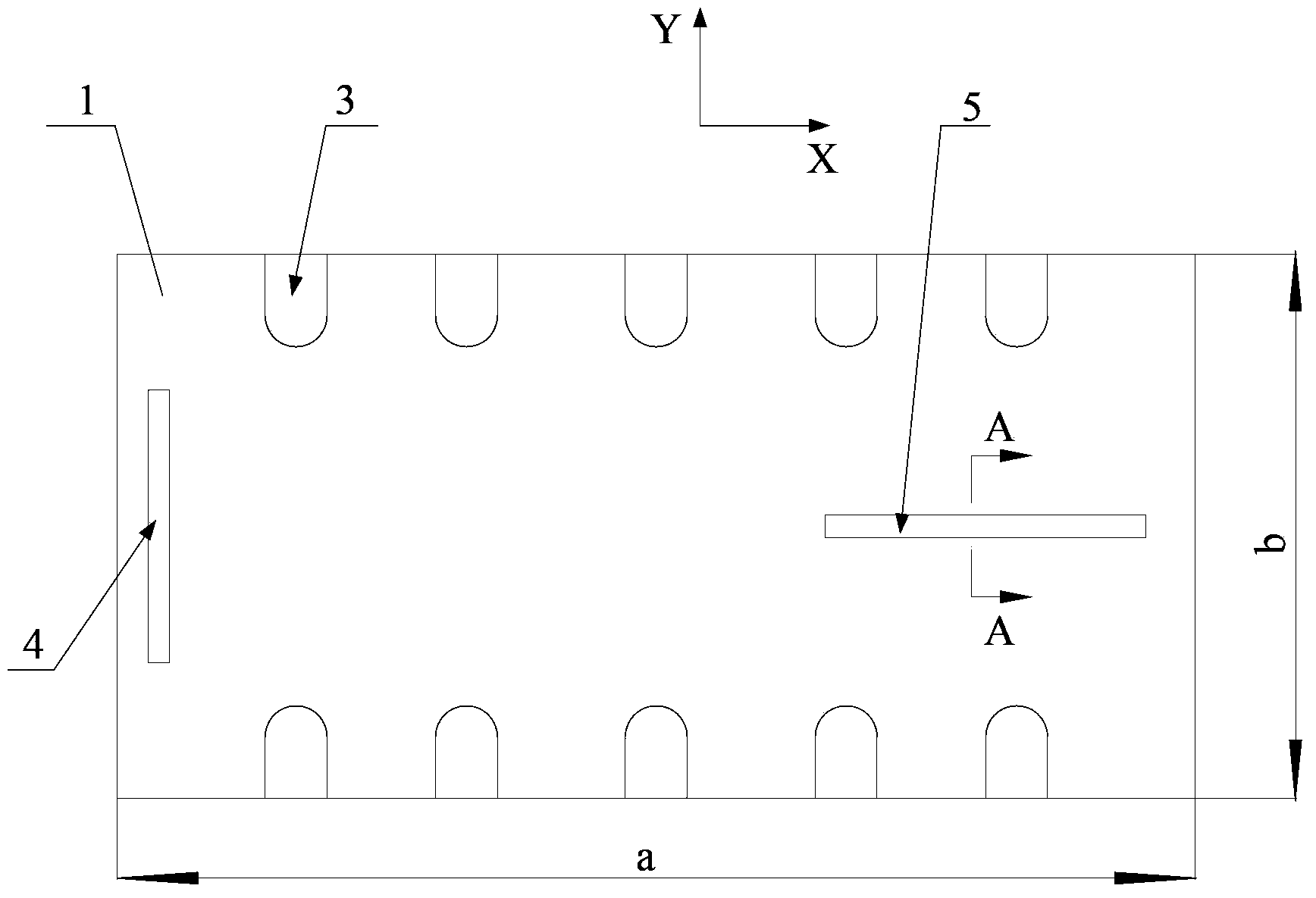
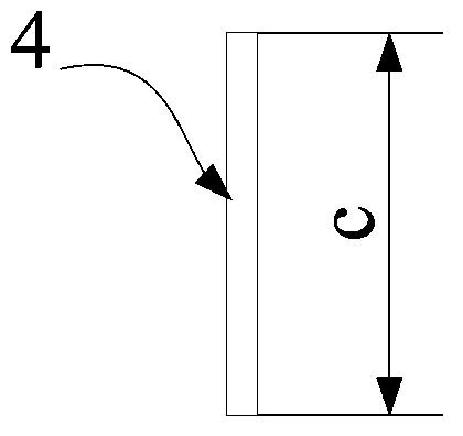
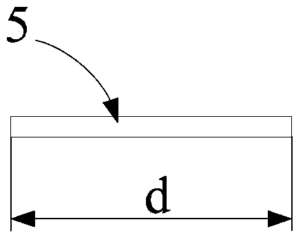
[0061] Figure 1 to Figure 5 A schematic structural view of a riveting positioning jig according to an embodiment of the present invention is shown.

[0062] Such as Figure 1 to Figure 5 As shown, the riveting positioning jig according to the embodiment of the present invention includes a jig body 1, a plurality of rivet mounting holes 3 are respectively provided on a set of opposite sides of the jig body 1, and t...


PUM

PropertyMeasurementUnit
pore sizeaaaaaaaaaa
pore sizeaaaaaaaaaa
lengthaaaaaaaaaa

Abstract

The invention provides a riveting and positioning fixture. The riveting and positioning fixture comprises a fixture body; two opposite sides of the fixture body are respectively provided with a plurality of rivet installation holes; one of the other two opposite sides of the fixture body is provided with a first positioning slide groove extending along a Y-axis direction, and the other of the other two opposite sides of the fixture body is provided with a second positioning slide groove extending along an X-axis direction; and a pin can slide in the first positioning slide groove and the second positioning slide groove and can be fixed at a designated position. The invention also provides a PCB riveting method, a manufacturing method for a PCB and the PCB. According to PCB riveting technology provided by the invention, riveting requirements of all standard jointed board products can be met only by manufacturing one riveting and positioning fixture, so production management is simplified; a pulling force generated in the riveting process can be effectively reduced, thereby avoiding scraping caused by dislocation and improving product yield; after pressing, rivets are drilled out through drilling, so the problems of board separation and delamination at positions where the rivets are located in later processing are overcome.

Description

technical field [0001] The invention relates to the field of PCB (Printed Circuit Board) manufacturing, more specifically, to a riveting positioning fixture, a PCB riveting method, a method for manufacturing a PCB, and a PCB. Background technique [0002] In the process of manufacturing PCB, the alignment accuracy between layers determines the ability of the platen. When the thickness of the core board is greater than 0.5mm and the matching structure is greater than 3 prepregs, the melt glue process cannot effectively fix the layers. At this time, the riveting process is required for production. [0003] However, the traditional riveting process is affected by the riveting method and the stress problem during the riveting process, which often leads to problems such as misalignment and loose riveting, which eventually lead to the scrapping of the board due to misalignment. At the same time, the traditional positioning fixtures are made separately according to each model, whi...

Claims


Application Information

Patent Timeline
Patent Type & Authority Applications(China)
IPC IPC(8): B29C65/60B25B11/00H05K3/00
Inventor 张贤仕
Owner PEKING UNIV FOUNDER GRP CO LTD
Why Eureka
Try Eureka