
Variable valve lift mechanism

A valve lift and variable technology, applied in mechanical equipment, engine components, machines/engines, etc., can solve the problems that the popularity is not as expected, and achieve no mutual interference, good linear output performance, and good linear control performance effect

Inactive Publication Date: 2014-06-11
SOUTH CHINA UNIV OF TECH
View PDF10 Cites 1 Cited by
  • Summary
  • Abstract
  • Description
  • Claims
  • Application Information

AI Technical Summary

Problems solved by technology

Although variable valve lift technology is gradually being applied to automobile engines, its popularity is far from expected

Method used


Image

  • Variable valve lift mechanism
  • Variable valve lift mechanism
  • Variable valve lift mechanism

Examples


Embodiment

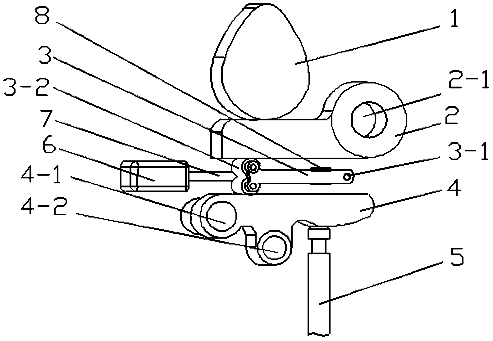
[0026] like figure 1 shown. The variable valve lift mechanism of the present invention includes an upper rocker arm 2, a lower rocker arm 4, and a valve 5. The right end of the upper rocker arm 2 has a round hole 2-1, and the upper surface of the upper rocker arm 2 is provided with a cam 1. , the upper surface and the lower surface of the upper rocker arm 2 are flat, and the lower surface of the cam 1 is in sliding contact with the upper surface of the upper rocker arm 2;

[0027] The left end of the lower rocker arm 4 has a hole for being sleeved on the positioning shaft 4-1 of the engine cylinder head. The upper surface of the lower rocker arm 4 is a plane, and the lower surface of the right end of the lower rocker arm 4 is an arc surface. ;

[0028] An intermediate rocker 3 is arranged between the upper rocker 2 and the lower rocker 4, the right end of the middle rocker 3 is provided with a mounting hole 3-1, and the left end is provided with two vertically symmetrical ro...


PUM

PropertyMeasurementUnit
Thicknessaaaaaaaaaa

Abstract

The invention discloses a variable valve lift mechanism, which comprises an upper rocker arm, a middle rocker arm, a lower rocker arm, a valve and a continuous regulation device, wherein a cam, the upper rocker arm and the middle rocker arm form a first group of levers, and the middle rocker arm, the lower rocker arm and the valve form a second group of levers, so that two groups of levers are formed; the middle rocker arm transversely displaces between the upper and lower rocker arms to change the amplification of the two groups of levers to further change the maximum lift of a valve. According to the variable valve lift mechanism, the maximum lift of the valve can be continuously regulated within a larger range, and the components of the mechanism are simple in structure and high in linear control performance, linear output performance and interchangeability.

Description

technical field [0001] The invention relates to the field of engine valve mechanism, in particular to a variable valve lift mechanism. Background technique [0002] The relative rotation angle between the camshaft and the crankshaft of the traditional engine valve train is fixed, and the cam profile on the camshaft is also fixed, which means that the valve opening phase, duration angle and valve lift are fixed. In order to meet the requirements of valve parameters under the two extreme working conditions of high-speed high-load dynamic performance and low-speed low-load emission performance, the traditional fixed design has been considered as the best compromise between these two working conditions for a long time. However, as the demands of all walks of life for high speed, low energy consumption, and low emissions become stronger and stronger, the valve mechanism must be changed accordingly according to the real-time working conditions of the engine. [0003] Applying var...

Claims


Application Information

Patent Timeline
IPC IPC(8): F01L13/00
Inventor 肖国权梁荣光王惜慧郭明林
Owner SOUTH CHINA UNIV OF TECH
Features
  • Generate Ideas
  • Intellectual Property
  • Life Sciences
  • Materials
  • Tech Scout
  • Unparalleled Data Quality
  • Higher Quality Content
  • 60% Fewer Hallucinations
Learn More