Calculation method of fatigue life of shaft parts

A technology of fatigue life and calculation method, applied in the direction of calculation, special data processing applications, instruments, etc., to achieve the effect of excellent universality, reasonable structure design, and reduction of analysis time

Active Publication Date: 2017-02-15
中国能建集团装备有限公司南京技术中心
View PDF4 Cites 0 Cited by
  • Summary
  • Abstract
  • Description
  • Claims
  • Application Information

AI Technical Summary

Problems solved by technology

However, the relevant results of such research are rarely reported at home and abroad.

Method used


Image

  • Calculation method of fatigue life of shaft parts
  • Calculation method of fatigue life of shaft parts
  • Calculation method of fatigue life of shaft parts

Examples


Embodiment Construction

[0025] Preferred embodiments of the present invention will be described in detail below in conjunction with the accompanying drawings.

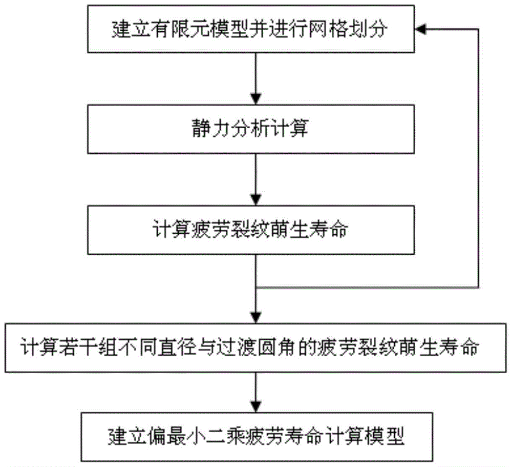
[0026] Such as figure 1 As shown, this embodiment provides a method for calculating the fatigue life of shaft parts, including the following steps:

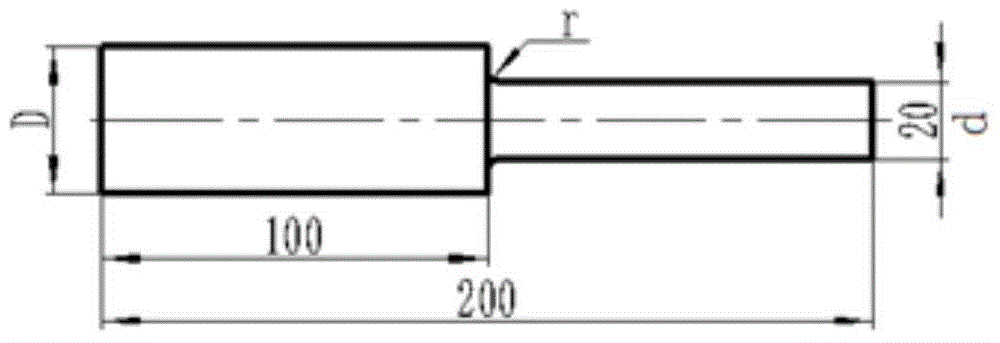
[0027] a. Establish a finite element model and carry out mesh division, use 3D software to establish a solid model of the measured shaft part, convert the solid model of the measured shaft part into a finite element model, perform finite element mesh division, and use The local fine mesh method performs fine mesh division on the transition fillet;

[0028] b. Static analysis and calculation. After defining the material and constraint conditions of the measured shaft parts and applying the load, perform static analysis and calculation to obtain the node where the maximum stress occurs;

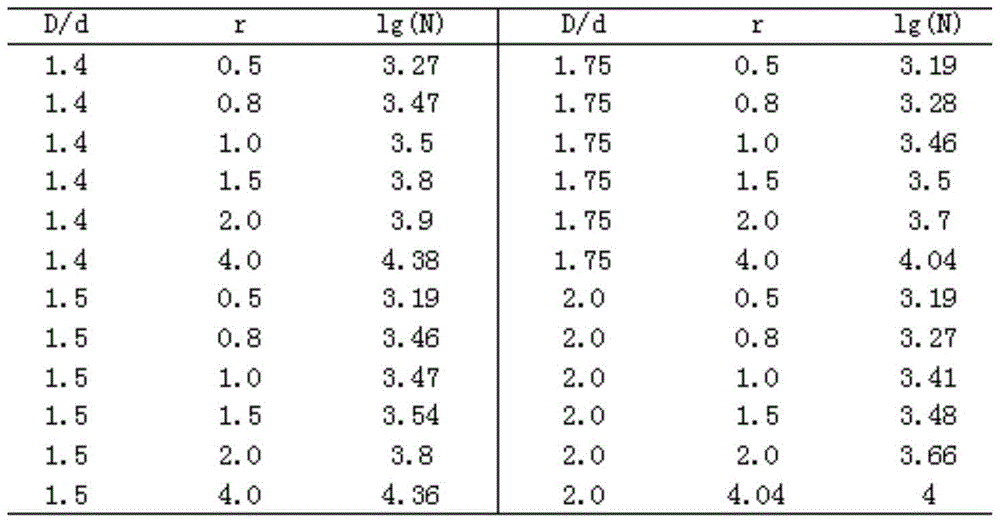
[0029] c. Calculate the fatigue crack initiation life, according to the simplified elastic-plastic theory an...


PUM


Abstract

The invention provides a fatigue life calculation method for shaft parts. The fatigue life of a shaft part is accurately calculated by steps of establishing a finite element model of the shaft part to be measured, dividing grids, analyzing and calculating a static force, calculating the initial lives of fatigue cracks, calculating the initial lives of a plurality of groups of fatigue cracks with different diameters and transition corners, and establishing a partial least square fatigue life calculation model. By adopting the fatigue life calculation method for shaft parts, the fatigue life of a shaft part can be accurately analyzed and the analysis time is greatly reduced. By adopting the fatigue life calculation method for shaft parts, the structure design of a shaft part is more reasonable and can be quantitatively controlled. The fatigue life calculation method for shaft parts has excellent universality and can be spread and applied to the design calculation of shaft parts made of other materials; the calculation result of the method is helpful for technicians to improve an existing calculation method and a reliable basis is provided to the structure design of a shaft part.

Description

technical field [0001] The invention relates to a method for calculating the fatigue life of shaft parts. Background technique [0002] Shafts are rotating or stationary parts, usually of circular cross-section. It may be subjected to bending, tensile, compressive or torsional loads during operation, and these loads may act alone or in combination. Stresses within a shaft may include static stresses, symmetric cyclic stresses, and pulsating cyclic stresses at the same time. When the shaft adopts a stepped structure, there is a large stress concentration at the shaft shoulder, which will have an adverse effect on the strength of the shaft. The arc transition at the shaft shoulder can effectively reduce stress concentration, and the selection of fillet size in the design is also very critical. [0003] For a long time, the fatigue calculation life design of shaft parts has been limited to traditional empirical design and general theoretical discussion, and the rounded corne...

Claims


Application Information

Patent Timeline
Patent Type & Authority Patents(China)
IPC IPC(8): G06F17/50
Inventor 徐志伟鲁加明陆桂来赵云陆巍
Owner 中国能建集团装备有限公司南京技术中心
Why Eureka
Try Eureka