
Power supply system, power module in power supply system and manufacturing method for power module

A power module and power system technology, applied in the direction of output power conversion devices, circuits, electrical components, etc.

Active Publication Date: 2014-06-11
DELTA ELECTRONICS INC
View PDF7 Cites 13 Cited by
  • Summary
  • Abstract
  • Description
  • Claims
  • Application Information

AI Technical Summary

Problems solved by technology

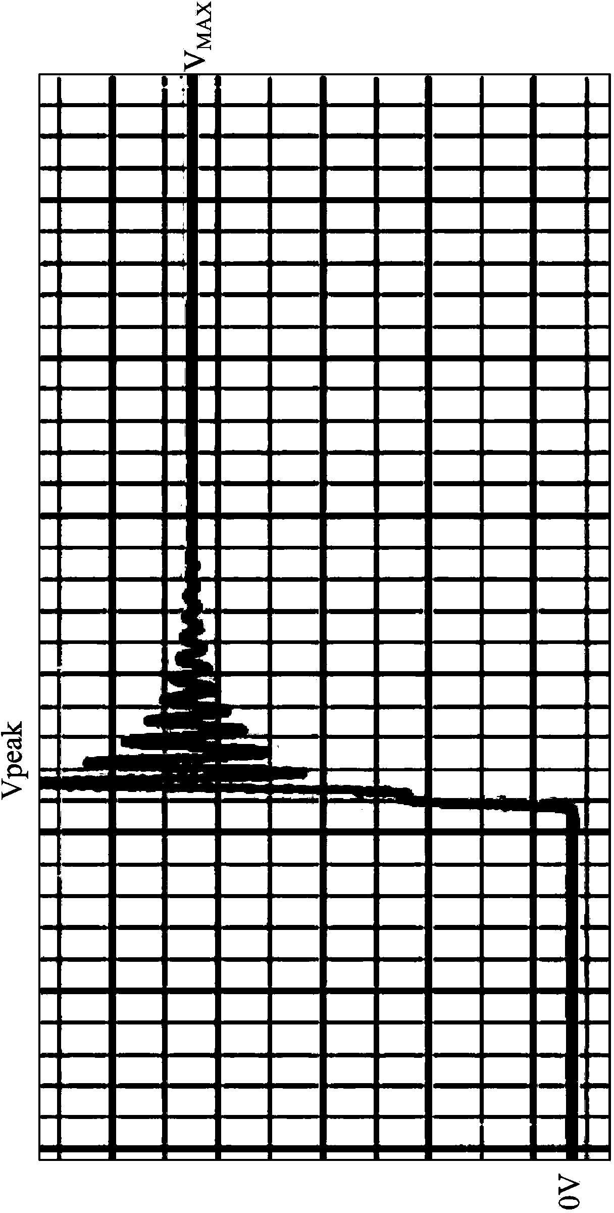
[0006] The content of the present invention is about a power supply system, a power module and a method for making a power module, thereby reducing electromagnetic interference generated during operation and improving the problem of voltage surges generated when the device is turned off

Method used


Image

  • Power supply system, power module in power supply system and manufacturing method for power module
  • Power supply system, power module in power supply system and manufacturing method for power module
  • Power supply system, power module in power supply system and manufacturing method for power module

Examples


Embodiment Construction

[0090] The following is a detailed description of the embodiments in conjunction with the accompanying drawings, but the provided embodiments are not intended to limit the scope of the present invention, and the description of the structure and operation is not intended to limit the order of execution, and any recombination of components The structure of the resulting device with equal efficacy is within the scope of the present invention. In addition, the drawings are for illustration purposes only and are not drawn to original scale. For ease of understanding, the same components will be described with the same symbols in the following description.

[0091] The terms (terms) used throughout the specification and claims, unless otherwise noted, generally have the ordinary meaning of each term as used in the field, in the disclosed content and in the special content. Certain terms used to describe the present disclosure are discussed below or elsewhere in this specification t...


PUM


Abstract

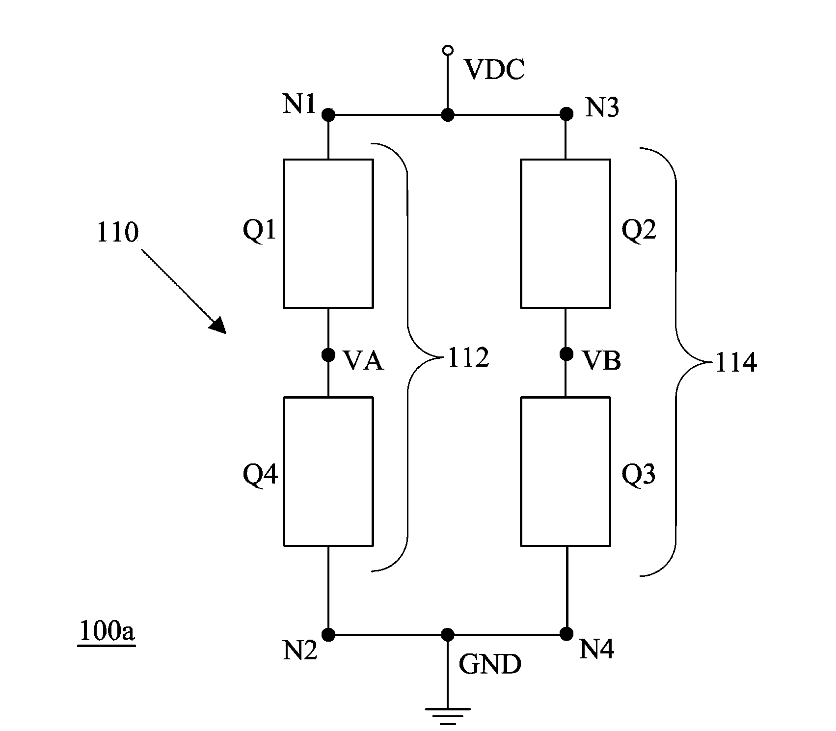
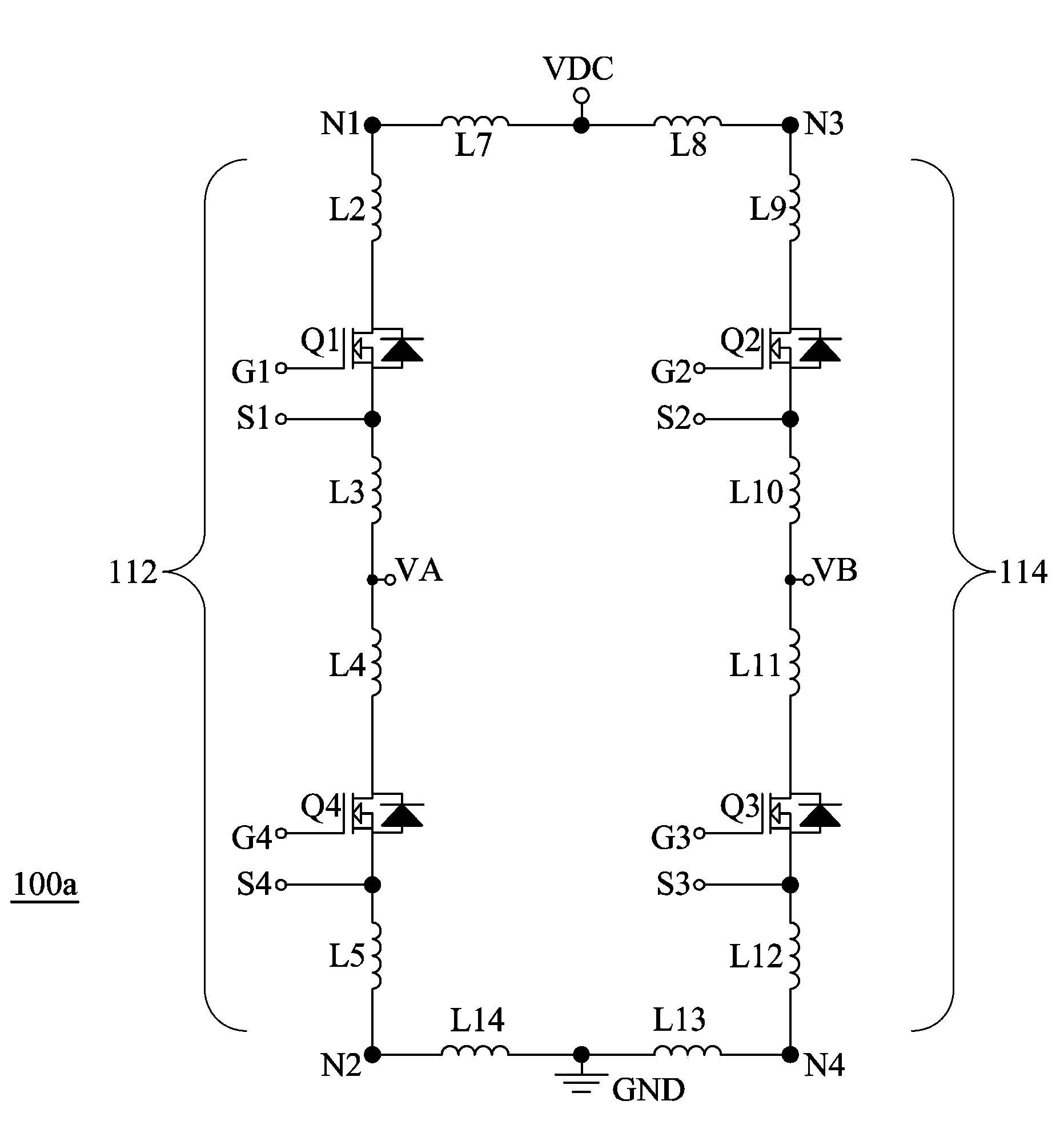
The invention discloses a power supply system, a power module in the power supply system and a manufacturing method for the power module. The power module comprises a first common pin, a second common pin, a first bridge arm and a second bridge arm. The first common pin and the second common pin are symmetrically arranged on one side of a substrate. The first bridge arm comprises a first semiconductor device and a second semiconductor device, wherein the first semiconductor device and the second semiconductor device are mutually connected through the first common pin and adjacently arranged. The second bridge arm comprises a third semiconductor device and a fourth semiconductor device, wherein the third semiconductor device and the fourth semiconductor device are mutually connected through the second common pin and adjacently arranged. The first semiconductor device and the third semiconductor device are symmetrically arranged, and the second semiconductor device and the fourth semiconductor device are symmetrically arranged.

Description

technical field [0001] The content of the present invention relates to a power module, and in particular to a power module applied in a power converter. Background technique [0002] High efficiency and high power density have always been the industry's requirements for power converters. High efficiency means reducing energy consumption, which is conducive to energy conservation and emission reduction to protect the environment and reduce use costs. High power density means small size and light weight, which is conducive to reducing transportation costs and space requirements, thereby reducing construction costs. At the same time, high power density also means reducing the amount of materials used, which is further conducive to energy saving and emission reduction to protect the environment. Therefore, in the field of power supplies, the pursuit of high efficiency and high power density will never stop. [0003] There are many types of power converters due to their differe...

Claims


Application Information

Patent Timeline
Patent Type & Authority Applications(China)
IPC IPC(8): H02M1/00H02M1/44H01L25/07H01L23/48H01L21/50
CPCH01L2924/1305H01L2924/13055H01L2924/13091H01L2924/19105H01L2224/0603H01L2224/48091H01L2224/48139H01L2224/48247H01L2224/48472H01L2224/49111H01L2224/49113Y02B70/10H01L2924/00014H01L2924/00
Inventor 曾剑鸿洪守玉郭雪涛
Owner DELTA ELECTRONICS INC
Learn More