Infrared remote control lamp

A remote control lamp and infrared technology, which is applied in the field of infrared remote control lamps, can solve the problems of increased cost, inapplicability, and high cost, and achieve the effects of convenient operation, simple structure, and low cost

Inactive Publication Date: 2014-06-11
CHONGQING ZHUOTE TECH
View PDF0 Cites 4 Cited by
  • Summary
  • Abstract
  • Description
  • Claims
  • Application Information

AI Technical Summary

Problems solved by technology

[0002] At present, there are mainly two types of lighting lamps: the first is a general lighting lamp that is turned on / off by pressing a switch installed on the wall. This kind of lighting lamp has a simple structure and low cost, and is mainly suitable for homes, offices, etc. However, the switch is installed on the wall, and it is inconvenient for children and the disabled to press the switch. When sleeping at night, after turning off the light, you need to go to bed in the dark, and when you turn on the light, you need to find the switch in the dark to turn on the light. Objects stumble, and in some harsh environments, such as factories with heavy smoke and poor light, it is not easy for people to find the switch on the wall. Therefore, this lighting has the disadvantage of being inconvenient to use
The second is voice-activated lighting, which controls the opening of the bulb through sound. This lighting is mainly used in corridors, aisles and other places because it does not need a switch. People can turn on the lights as long as they make enough sounds, but other Not suitable for home, office, factory and other places, because once the sound disappears, the light will go out, affecting people's use
[0003] Later, people designed a switch with infrared remote control function. For example, the remote control of TV sets and air conditioners is controlled by infrared. The cost is high. If it is used to control lighting, the cost will be greatly increased due to the large number of lighting used in each family or unit.

Method used


Image

  • Infrared remote control lamp
  • Infrared remote control lamp

Examples


Embodiment Construction

[0012] The present invention will be further described below in conjunction with accompanying drawing.

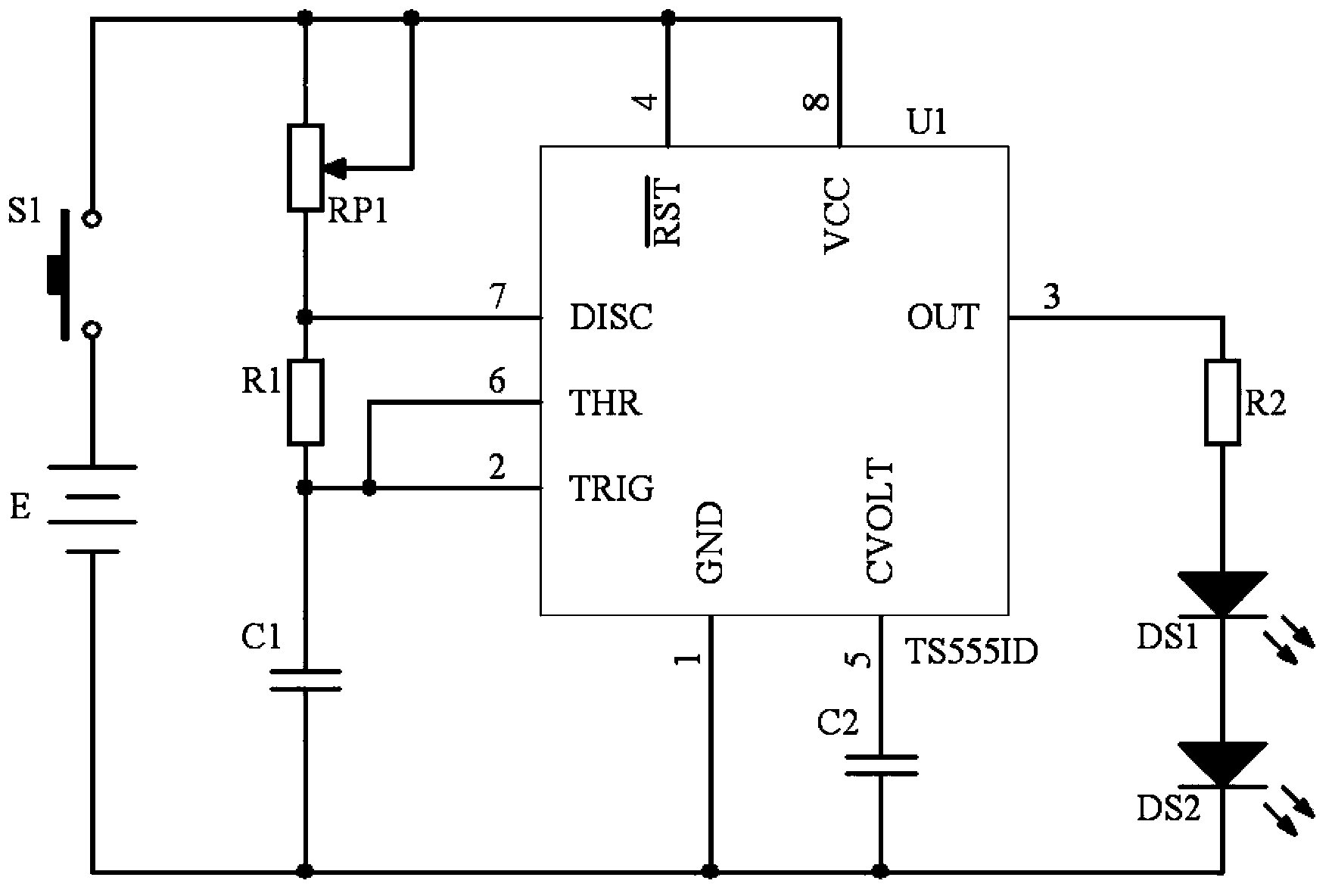
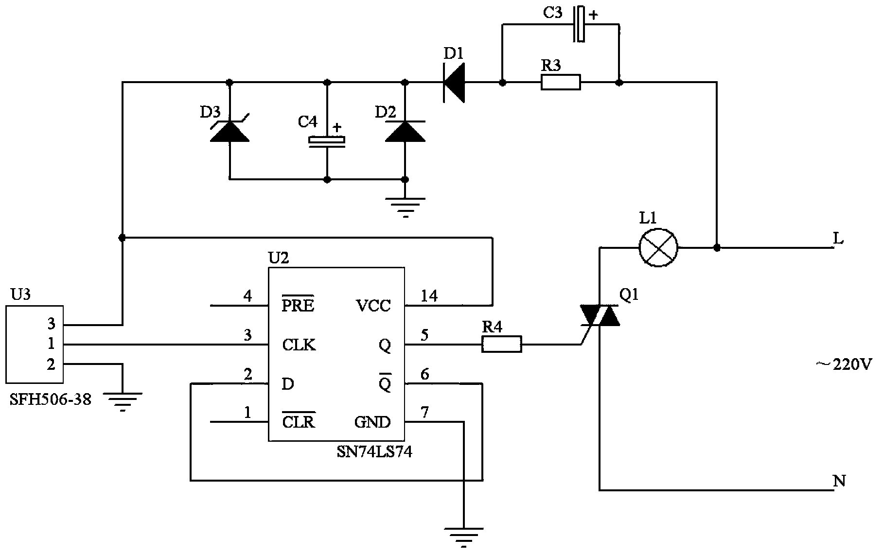
[0013] like figure 1 , figure 2 The infrared remote control lamp shown, including infrared transmitter, infrared receiver, actuator and bulb L1;

[0014] Among them, the infrared emitter includes a button S1, a battery E, an adjustable resistor RP1, a first resistor R1, a first capacitor C1, a 555 timer U1 whose model is TS555ID, a second capacitor C2, a second resistor R2 and a first infrared light emitter Diode DS1, second infrared light-emitting diode DS2, one end of the button S1 is connected to the positive pole of the battery E, the other end is connected to one end of the adjustable resistor RP1, the other end of the adjustable resistor RP1 is connected to one end of the first resistor R1, and the other end of the first resistor R1 The other end is connected to one end of the first capacitor C1, the other end of the first capacitor C1 is connected to the negative ...


PUM


Abstract

The invention discloses an infrared remote control lamp comprising an infrared emitter, an infrared receiver, an actuator and a bulb. The infrared emitter comprises a button, a battery, an adjustable resistor, a first resistor, a first capacitor, a 555 timer, a second capacitor, a second resistor and first and second infrared light-emitting diodes. The actuator adopts a bidirectional silicon controlled rectifier. The infrared receiver comprises an infrared receiving head with a model number of SFH506-38, a double-D trigger with the model number of SN74LS74, a fourth resistor and a voltage-reducing rectification filter circuit. The remote control lamp is simple in remote control circuit structure and low in cost so that the remote control lamp can be applied to occasions like households, offices or factories with server environment, and thus operation of turning on/off the lamp can be facilitated for people.

Description

technical field [0001] The invention relates to an illuminating lamp, in particular to an infrared remote control lamp. Background technique [0002] At present, there are mainly two types of lighting lamps: the first is a general lighting lamp that is turned on / off by pressing a switch installed on the wall. This kind of lighting lamp has a simple structure and low cost, and is mainly suitable for homes, offices, etc. However, the switch is installed on the wall, and it is inconvenient for children and the disabled to press the switch. When sleeping at night, after turning off the light, you need to go to bed in the dark, and when you turn on the light, you need to find the switch in the dark to turn on the light. Objects are tripped, and in some harsh environments, such as factories with heavy smoke and poor light, it is not easy for people to find the switch on the wall. Therefore, this lighting has the disadvantage of being inconvenient to use. The second is voice-activ...

Claims


Application Information

Patent Timeline
Patent Type & Authority Applications(China)
IPC IPC(8): H05B37/02
Inventor 叶会英张庆彬钱红英张庆凤
Owner CHONGQING ZHUOTE TECH
Why Eureka
Try Eureka