Supercharge Your Innovation With Domain-Expert AI Agents!

Double-circular-mold biomass particle forming machine

A biomass pellet and pellet molding machine technology, applied in the direction of die extrusion and pelletization, can solve the problems of waste of resources, low production efficiency, environmental pollution, etc., and achieve total cost reduction, machine wear reduction, and production efficiency improvement. Effect

Inactive Publication Date: 2014-06-18
JIANGSU UNIV
View PDF9 Cites 6 Cited by
  • Summary
  • Abstract
  • Description
  • Claims
  • Application Information

AI Technical Summary

Problems solved by technology

Because these crop straws are not fully utilized, a large amount of incineration has become a major social problem, which not only wastes resources, but also seriously pollutes the environment. The solidification and molding of straws is a good way to solve this problem; the pellet molding machine adopts ring molding die holes , has the advantages of high stability and low energy consumption. It is one of the mainstream equipment for straw solidification and molding that is widely used at present; the patent number is: 201210455418.2, the patent number is: ZL200720158058.4, the patent number is: ZL200710114897.0 and the patent The invention patent No.: ZL 200810022426.1 proposes a new ring die pellet forming machine structure, which also solves many problems in the pelletizing process. The disadvantage of not being high is not suitable for commercial applications

Method used


Image

  • Double-circular-mold biomass particle forming machine
  • Double-circular-mold biomass particle forming machine
  • Double-circular-mold biomass particle forming machine

Examples


Embodiment 1)

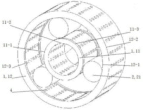
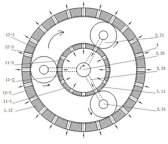
[0031] The present invention includes a power system and a feeding device not shown in the accompanying drawings, and figure 1 The pellet molding machine body shown in , the pellet molding machine body includes a ring die set 1, a press roller set 2 and a press roll drive mechanism 3 connected to the power system; the ring die set 1 consists of an inner ring die 11 and an outer ring die 12 components, the inner ring die 11 and the outer ring die 12 are equipped with granulation holes 4; the pressing roller group 2 is arranged between the inner and outer ring dies and cooperates with the inner and outer ring dies; the pressing rollers drive The mechanism is located between the pressing roller group 2 and the inner ring die 11 .

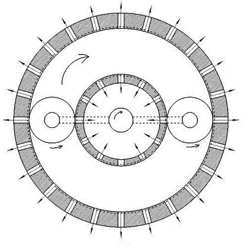
[0032] According to different types of granulators, the pressure roller group 2 of the present invention can be composed of 1 to 4 pressure rollers 21. Generally, the number of pressure rollers is selected on the basis of considering the space between ...


PUM


Abstract

The invention relates to a particle forming machine, and in particular relates to a double-circular-mold biomass particle forming machine. The double-circular-mold biomass particle forming machine comprises a particle forming machine body, a power system and a material feeding device, wherein the particle forming machine body comprises a circular mold group, a pressing roller group and a pressing roller driving mechanism connected with the power system; the circular mold group consists of an inner-layer circular mold and an outer-layer circular mold; granulation holes are formed in the inner-layer circular mold and the outer-layer circular mold; the pressing roller group is arranged between the inner-layer circular mold and the outer-layer circular mold and is matched with the inner-layer circular mold and the outer-layer circular mold; the pressing roller driving mechanism is positioned between the pressing roller group and the inner-layer circular mold. According to the double-circular-mold biomass particle forming machine, pressing rollers are arranged between the inner-layer circular mold and the outer-layer circular mold; when rotating, the pressing rollers can be squeezed and formed with the inner-layer circular mold and the outer-layer circular mold at the same time; compared with a conventional technical method, the granulation method has the advantage that the energy consumption of tonnage fuel can be reduced by 50-60 percent under a condition of same yield; the double-circular-mold biomass particle forming machine is simple in structure, low in cost, high in stability and high in production efficiency.

Description

technical field [0001] The invention relates to a granule forming machine, in particular to a double-ring mold biomass granule forming machine. Background technique [0002] Crop straw is a precious resource. my country is a large agricultural country with abundant straw resources. The annual output of crop straw in China is about 700 million tons, ranking first in the world. Because these crop straws are not fully utilized, a large amount of incineration has become a major social problem, which not only wastes resources, but also seriously pollutes the environment. The solidification and molding of straws is a good way to solve this problem; the pellet molding machine adopts ring molding die holes , has the advantages of high stability and low energy consumption. It is one of the mainstream equipment for straw solidification and molding that is widely used at present; the patent number is: 201210455418.2, the patent number is: ZL200720158058.4, the patent number is: ZL20071...

Claims


Application Information

Patent Timeline
IPC IPC(8): B01J2/22
Inventor 陈树人段建
Owner JIANGSU UNIV
Features
  • R&D
  • Intellectual Property
  • Life Sciences
  • Materials
  • Tech Scout
  • Unparalleled Data Quality
  • Higher Quality Content
  • 60% Fewer Hallucinations
Learn More