Positioning and clamping mechanism for welding of rear stabilizer bar mounting bracket of rear subframe
A technology for positioning, clamping and mounting brackets, applied in welding equipment, welding equipment, welding accessories, etc., it can solve problems such as poor clamping effect, and achieve the effect of improving welding efficiency, meeting accessibility requirements, and positioning accurate positions.
- Summary
- Abstract
- Description
- Claims
- Application Information
AI Technical Summary
Problems solved by technology
Method used
Image
Examples
Embodiment 1
[0031] Example 1 A positioning and clamping mechanism for welding the rear stabilizer bar mounting bracket of the rear sub-frame
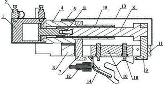
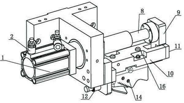
[0032] This embodiment is a positioning and clamping unit, which is used to clamp the rear stabilizer bar installation bracket of the rear sub-frame on the left side, that is, the workpiece 14 .
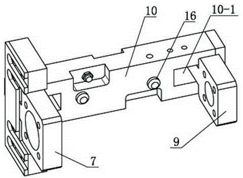
[0033] The positioning and clamping unit includes a reference platform, which is composed of a base 3 on the left and a support block 10 on the right in solid connection. A cylinder 1 with a cylinder body that can slide left and right along the reference platform is freely placed above the reference platform, and the telescopic rod of the cylinder 1 stretches left and right.
[0034] The positioning and clamping unit also includes a left jaw 1 and a right jaw 9 that move axially due to the horizontal movement of the cylinder 1, such as image 3 shown. Left claw 7 such as Figure 4 As shown, it is firmly connected with the cylinder body. The right cl...
Embodiment 2
[0053] Example 2 A positioning and clamping mechanism for welding the rear stabilizer bar mounting bracket of the rear sub-frame
[0054] This embodiment is a positioning and clamping unit, which is used for clamping the rear stabilizer bar mounting bracket of the rear sub-frame on the right side. The positioning and clamping unit is an equivalent replacement made according to the essence of embodiment 1, and is used for clamping the rear stabilizer bar mounting bracket of the rear sub-frame on the left side.
[0055] The overall structure of this embodiment is symmetrical with the structure provided by Embodiment 1 with respect to the vertical plane along the extension direction of the telescopic rod; example 1 figure 1 The structure of the workpiece 14 in the left and right sides is symmetrical.
[0056] The working principle of this embodiment is the same as that of Embodiment 1, and the working process is corresponding.
Embodiment 3
[0057] Example 3 A positioning and clamping mechanism for welding the rear stabilizer bar mounting bracket of the rear sub-frame
[0058] This embodiment includes two positioning and clamping units, which are set apart from each other on the left and right sides. The structure of the unit relatively on the left is exactly the same as that of Embodiment 1, and the working principle and working process are also exactly the same and located on the left; the structure of the unit relatively located on the right is exactly the same as that of Embodiment 2, and is located on the right.
[0059] Both units work simultaneously. Such as Image 6 As shown, when the present embodiment works, the two positioning and clamping units are assembled on the horizontal sliding table 19 connected with the main body table of the integral welding tool through the longitudinal sliding table 18. The whole tooling is an existing product, which is used for welding between the stabilizer bar mountin...
PUM
 Abstract
Description
Claims
Application Information
 - R&D
- Intellectual Property
- Life Sciences
- Materials
- Tech Scout
- Unparalleled Data Quality
- Higher Quality Content
- 60% Fewer Hallucinations
Browse by: Latest US Patents, China's latest patents, Technical Efficacy Thesaurus, Application Domain, Technology Topic, Popular Technical Reports.
© 2025 PatSnap. All rights reserved.Legal|Privacy policy|Modern Slavery Act Transparency Statement|Sitemap|About US| Contact US: help@patsnap.com


