Modular catalytic hydrogenation deoxygenation apparatus for nuclear power station

A catalytic hydrogenation and modular technology, applied in the direction of reduced water/sewage treatment, degassed water/sewage treatment, etc., can solve the problems of hydrogen discharge safety, increased operating costs, and difficulty in ensuring quality and project progress. Safe and convenient maintenance and reliable operation

Inactive Publication Date: 2014-06-18
武汉海王新能源工程技术有限公司
View PDF0 Cites 3 Cited by
  • Summary
  • Abstract
  • Description
  • Claims
  • Application Information

AI Technical Summary

Problems solved by technology

Catalytic hydrogenation technology is usually used to remove oxygen. This technology has wide application range, high oxygen removal efficiency, large processing capacity, no pollution and side effects. However, in order to make the dissolved oxygen in the treated water supply as low as possible, excessive hydrogenation is often used operating mode, which brings about the increase of operating cost and the safety issue of hydrogen emission
At the same time, the implementation of this technology requires multiple pieces of equipment, valves, pipelines, and instruments. Among them, the main equipment is shipped to the site after processing in the factory, and the connecting pipelines, valves, and instruments are installed on the construction site. Due to the large number of related interfaces And on-site production conditions are limited, especially the working environment has the risk of radioactive pollution, and its quality and project progress are often difficult to guarantee

Method used


Image

  • Modular catalytic hydrogenation deoxygenation apparatus for nuclear power station
  • Modular catalytic hydrogenation deoxygenation apparatus for nuclear power station
  • Modular catalytic hydrogenation deoxygenation apparatus for nuclear power station

Examples


Embodiment Construction

[0012] The present invention will be described in further detail below in conjunction with accompanying drawing and specific embodiment, but this embodiment should not be construed as limiting the present invention:

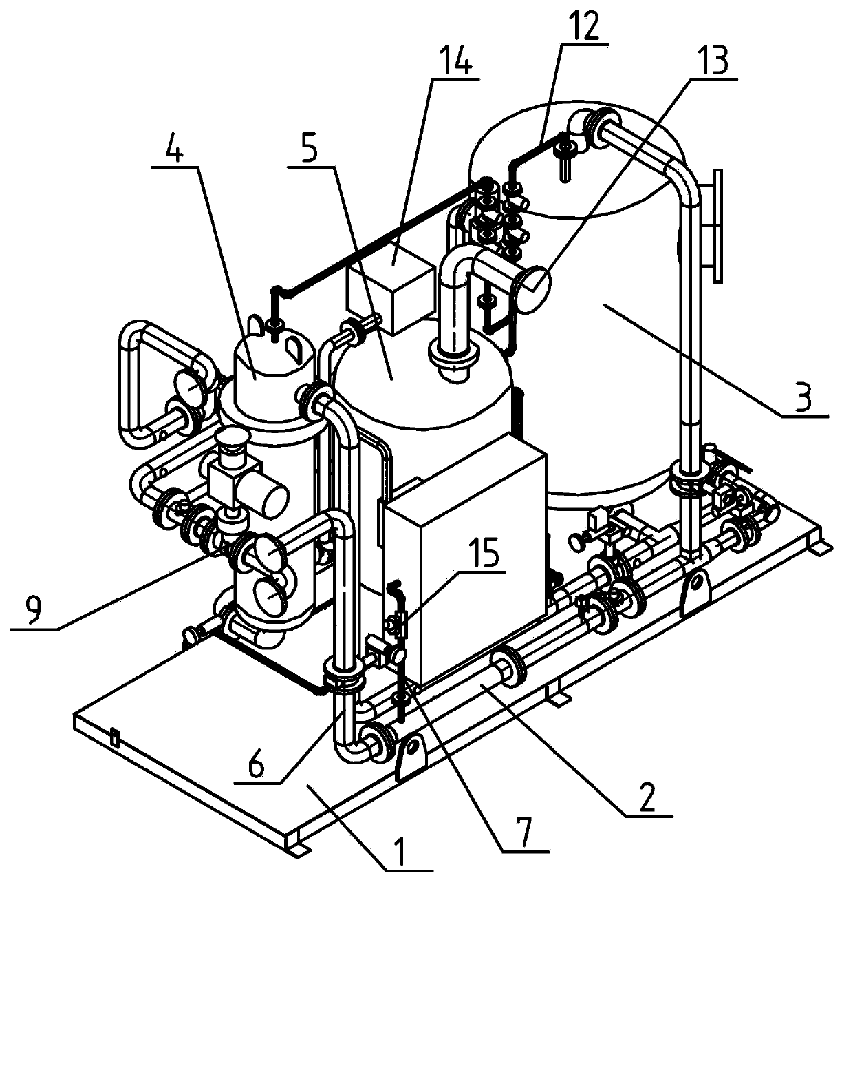
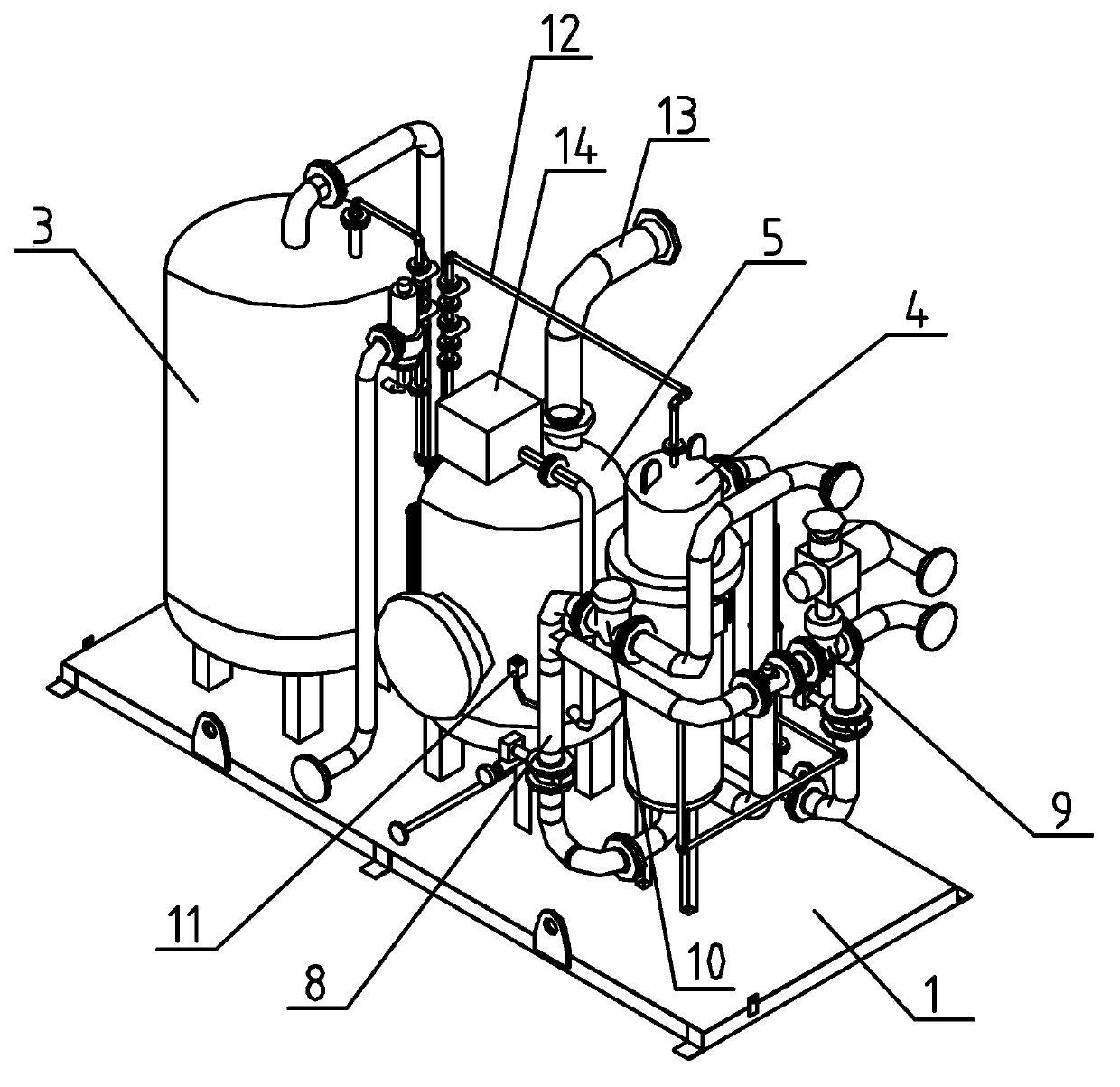
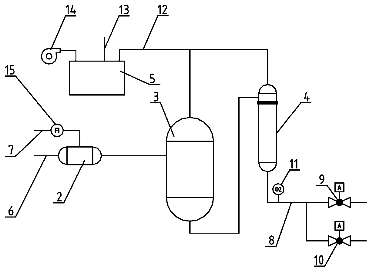
[0013] The modular catalytic hydrogenation deoxygenation device for nuclear power plants shown in the figure includes base 1, mixer 2, resin deoxygenation tank 3, resin trap 4 and degassing tank 5, mixer 2, resin deoxygenation tank 3, The resin catcher 4 and the degassing tank 5 are fixed on the base 1 respectively, the mixer 2 is connected with a water inlet pipe 6 and a hydrogenation pipe 7, the water outlet of the mixer 2 is connected with the water inlet of the resin deaeration tank 3, and the resin deoxidizer The water outlet of the oxygen tank 3 is connected with the water inlet of the resin trap 4, and the bottom of the resin trap 4 is connected with the water outlet valve 9 and the circulation valve 10 through the water outlet pipe 8, and the dissolved oxy...


PUM


Abstract

The invention relates to a catalytic hydrogenation deoxygenation apparatus for a nuclear power station. The apparatus comprises a pedestal, a mixer, a resin deoxygenation tank, a resin trapper and a degassing tank, the mixer, the resin deoxygenation tank, the resin trapper and the degassing tank are respectively fixed on the pedestal, the mixer is connected with a water inlet pipe and a hydrongeation pipe, the water outlet of the mixer is connected with the water inlet of the resin deoxygenation tank, the water outlet of the resin deoxygenation tank is connected with the water inlet of the resin trapper, the bottom of the resin trapper is connected with a water outlet valve and a circulation valve through the water outlet pipe, the water outlet pipe is provided with a dissolved oxygen analyzer, the top of the resin deoxygenation tank and the top of the resin trapper are connected with the degassing tank through exhaust pipes, the top of the degassing tank is provided with a gas outlet, and the wind outlet of a fan is connected with the degassing tank. The catalytic hydrogenation deoxygenation apparatus is integrated on a pedestal, is debugged and then is integrally conveyed to a site, so the apparatus is safe and convenient to install, debug, use and repair.

Description

technical field [0001] The invention relates to a catalytic hydrogenation and oxygen removal device, in particular to a modular catalytic hydrogenation and oxygen removal device for nuclear power plants. Background technique [0002] The existence of dissolved oxygen in water is an important cause of corrosion of power plant system equipment and pipelines, so nuclear power plants have particularly strict requirements on the oxygen content of operating water. Catalytic hydrogenation technology is usually used to remove oxygen. This technology has wide application range, high oxygen removal efficiency, large processing capacity, no pollution and side effects. However, in order to make the dissolved oxygen in the treated water supply as low as possible, excessive hydrogenation is often used The operation mode of the system brings about the increase of operating cost and the safety issue of hydrogen emission. At the same time, the implementation of this technology requires mult...

Claims


Application Information

Patent Timeline
Patent Type & Authority Applications(China)
IPC IPC(8): C02F1/20C02F1/70
Inventor 刘玲学马斌陈权陶林撷丁伯才赵红岗周折甘舒澜
Owner 武汉海王新能源工程技术有限公司
Why Eureka
Try Eureka