A milling rotor

A technology for milling rotors and rotors is applied in the field of road milling machines, which can solve the problems of unfavorable slag collection and large cutting resistance, and achieve the effects of improving the aggregate rate and the exhaust rate, ensuring the milling effect and reducing the difficulty of replacement.

Active Publication Date: 2017-01-18
王黎宏
View PDF9 Cites 0 Cited by
  • Summary
  • Abstract
  • Description
  • Claims
  • Application Information

AI Technical Summary

Problems solved by technology

[0003] The purpose of the present invention is to provide a milling rotor, which solves the shortcomings of the existing milling rotors, such as large cutting resistance and unfavorable collection of slag.

Method used


Image

  • A milling rotor
  • A milling rotor
  • A milling rotor

Examples


Embodiment Construction

[0015] The present invention will be described in detail below in combination with specific embodiments.

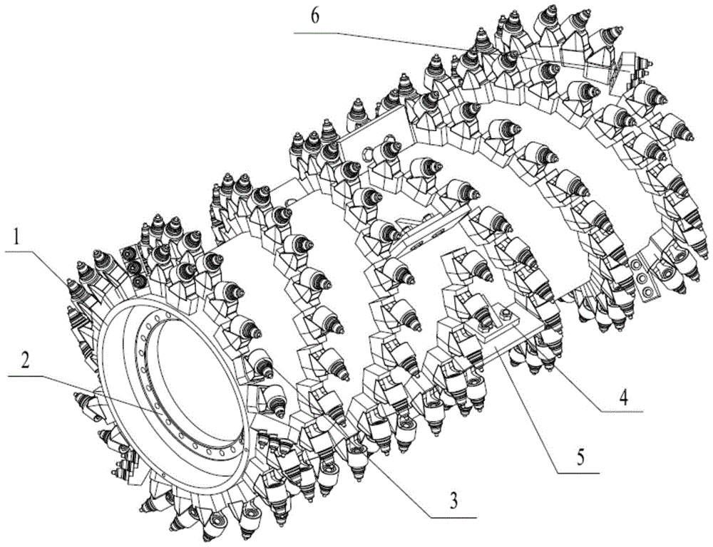
[0016] The structure of a milling rotor provided by the invention is as follows: figure 1 As shown, it includes a cylinder 1, the inner wall of the cylinder 1 is provided with a rotor reducer mounting flange 2, and the outer wall of the cylinder 1 is provided with a plurality of cutter assemblies 3, and the plurality of cutter assemblies 3 are arranged along the cylinder 1. Two groups of helical lines in opposite directions are arranged from the middle to both ends. The middle of the cylinder body 1 is located at the starting point of the helix. There is also a beating plate mounting flange 4. Sheet 5.

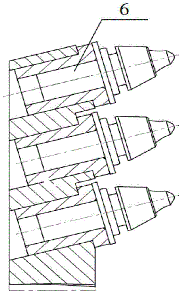
[0017] Such as figure 2 As shown, the cutter assembly 3 at the end of both ends of the barrel 1 is provided with a protective cutter assembly 6 .

[0018] The knockout plate 5 is fixed on the knockout plate flange 4 by bolts.

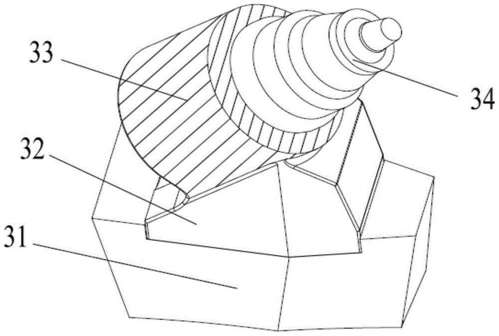
[0019] Such as image 3 and Figure 4...


PUM


Abstract

The invention discloses a milling-planing rotor. The milling-planing rotor comprises a cylinder body, wherein a rotor reducer mounting flange is arranged on the inner wall of the cylinder body, a plurality of cutter subassemblies are arranged on the outer wall of the cylinder body and are distributed in two groups of spiral lines along inverse directions from the middle part of the cylinder body to the two ends, and a knockout plate mounting flange is also arranged at the initial point positions of the spiral lines at the middle part of the cylinder body and is provided with a knockout plate. Due to the adoption of the milling-planing rotor, the problems that an existing milling-planing rotor is large in cutting resistance and inconvenient in material slag collection are solved; as the spiral lines are connected end to end smoothly, the resistance of the milling-planing rotor when a pavement is cut is weakened, the material collection ratio and the exhausted ratio are also greatly increased when the milling efficiency is ensured, the service life of each cutter is also prolonged, the later maintenance cost is reduced, and the changing difficulties of a cutter holder and the knockout plate are also greatly weakened.

Description

technical field [0001] The invention belongs to the technical field of road surface milling machines, and in particular relates to a milling rotor. Background technique [0002] The road milling machine is one of the main models for road maintenance. It is used for maintenance of ruts, carbuncles, cracks and other diseases on the road surface, that is, through the milling rotor system installed at the bottom of the milling machine, the damaged The road surface is milled into slag, so that the road surface can be repaired after removal. Surface mining machinery is mostly used in open-pit mining. The principle is the same as that of road milling machines, except that in order to ensure the uniformity of the mineral particles, the distance between the knife tips on the milling rotor is different, so as to ensure the minerals of the required specifications. Milling slag or mined minerals are collected by helical knives on the milling rotor when they are collected. The spiral c...

Claims


Application Information

Patent Timeline
Patent Type & Authority Patents(China)
IPC IPC(8): E01C23/088
Inventor 王黎宏
Owner 王黎宏
Why Eureka
Try Eureka