Heat dissipating system

A heat dissipation system and heat exchanger technology, applied in air cooling, engine components, machines/engines, etc., can solve problems such as poor heat dissipation effect and low fan blowing rate

Inactive Publication Date: 2014-06-18
LIUZHOU LIUGONG EXCAVATORS +2
View PDF7 Cites 1 Cited by
  • Summary
  • Abstract
  • Description
  • Claims
  • Application Information

AI Technical Summary

Problems solved by technology

[0008] The object of the present invention is to provide a method to avoid the fan blades from contacting with the wind guide in the existing heat dissipation system in order to solve the disadvantages of low fan blowing rate and poor heat dissipation effect due to the large gap area between the wind guide cover and the fan blade tip in the existing cooling system. A heat dissipation system that reduces the gap area between the air guide cover and the fan blade tip in the case of collision interference of the cover, and improves the blowing rate and heat dissipation effect of the fan

Method used


Image

  • Heat dissipating system
  • Heat dissipating system
  • Heat dissipating system

Examples


Embodiment 1

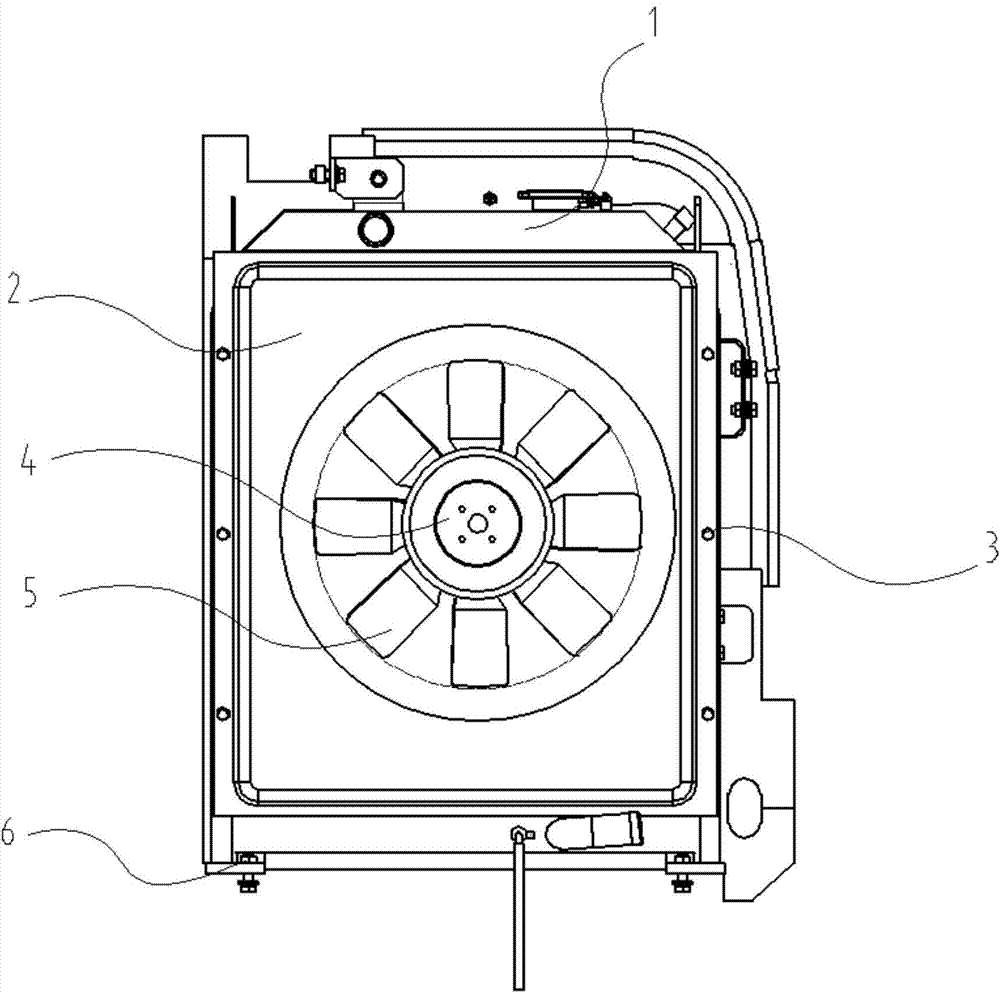
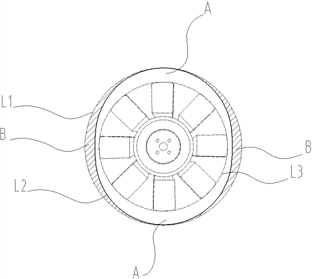
[0020] Such as figure 2 image 3 As shown, in this embodiment, the heat exchanger 1 is fixedly installed on the vehicle frame through the mounting bolts 6 , and the wind guide cover 2 is fixed on the heat exchanger 1 through the fixing bolts 3 to form an air duct. The fan 5 is directly connected to the engine through the fan spacer 4, and the fan is located in the inner hole of the air guide cover and is driven by the engine to drive the air flow to generate wind, which flows through the heat exchanger to achieve cooling effect. In this embodiment, the center of the fan is coaxial with the center of the inner hole of the air guide cover, and the fan rotates its fan blade tip under static conditions to form a circular trajectory line L3, and the opening inner hole of the air guide cover corresponding to the fan is set as an oblong hole, The long diameter direction of the oblong hole is the vertical direction, the radial distance from a point on the circular locus line to the ...

Embodiment 2

[0023] Compared with Example 1, the difference lies in the shapes of the left and right sides of the inner hole of the air guide cover, such as Figure 4 As shown, in this embodiment, in the contour line of the inner hole of the air guide cover, there are two arcs on the left and right sides, and the radius of curvature of the arcs gradually decreases as the arc extends to the upper and lower ends and is finally equal to the upper and lower circles The radius of the arc. L2 is the contour line of the inner hole of the windshield in this embodiment, and the contour line is left-right asymmetrical, wherein the radial distance from the inner hole contour line on the left side to the static trajectory line of the fan blade tip is greater than that on the right side from the inner hole contour line to The radial distance of the static trajectory line of the fan blade tip, L4 is the contour line of the inner hole of the air guide cover in Embodiment 1, and the closed area surrounded...


PUM


Abstract

The invention relates to a heat dissipating system. The heat dissipating system is used for solving the disadvantages of the existing heat dissipating systems that the air blasting rate of a fan is relatively low and the heat dissipating effect is poor caused due to the fact that the gap area between an air guiding hood and tips of fan blades is too large. The heat dissipating system provided by the invention comprises a heat exchanger and a fan facing to the heat exchanger, wherein an air guiding hood of a ventilating duct is formed between the fan and the heat exchanger, the fan is located in the air guiding hood, the internal hole of a position, where the fan is located, of the air guiding hood is a long circular hole, and the size of the long circular hole in the horizontal direction is smaller than that of the long circular hole in the vertical direction. According to the heat dissipating system, the characteristic that upward-downward vibration amplitude of an engine directly driven fan is greater than left-right horizontal vibration amplitude of the engine directly driven fan is utilized, the internal hole of the air guiding hood is designed into the long circular hole, then, the gap demand on upward-downward vibration of the fan is guaranteed, and gaps between the left and right sides of the air guiding hood and the tips of the fan blades are reduced, so that the air blasting rate of the fan is increased, and then, the heat dissipating effect of a heat dissipater is improved.

Description

technical field [0001] The invention relates to a cooling system, in particular to a cooling system for engineering machinery. Background technique [0002] As a cooling device for a construction machine, it generally has a heat exchanger that dissipates heat from a fluid flowing inside; a fan that is disposed facing the heat exchanger and generates cooling air supplied to the heat exchanger; and a cover formed on the The space between the fan and the heat exchanger and the air hood that forms the air passage between the fan and the heat exchanger. The fan is directly driven by the engine. [0003] However, in most practical applications, the vibration of the engine relative to the frame is that the displacement in the up and down direction is greater than the displacement in the horizontal direction. For example, when the engine is started, due to the piston movement characteristics of the engine, the engine will violently move up and down; and for example, when the crawl...

Claims


Application Information

Patent Timeline
Patent Type & Authority Applications(China)
IPC IPC(8): F01P1/00F01P11/10
Inventor 钟科俊刘晓强冯立霞
Owner LIUZHOU LIUGONG EXCAVATORS
Why Eureka
Try Eureka