Variable speed double-piston series-connection hydraulic cylinder

A series hydraulic cylinder and speed conversion technology, applied in the field of hydraulic cylinders, can solve the problems of complex structure, difficult maintenance and high cost of variable variable pumps, and achieve the effects of simplifying structure and control, reducing machining accuracy and saving energy

Inactive Publication Date: 2014-06-18
WUHAN UNIV OF SCI & TECH
View PDF11 Cites 4 Cited by
  • Summary
  • Abstract
  • Description
  • Claims
  • Application Information

AI Technical Summary

Problems solved by technology

However, the structure of the variable variable pump is complicated, the cost is high, the failure rate is high, and the maintenance is difficult, which increases the price of the whole hydraulic equipment.

Method used


Image

  • Variable speed double-piston series-connection hydraulic cylinder
  • Variable speed double-piston series-connection hydraulic cylinder

Examples


Embodiment 1

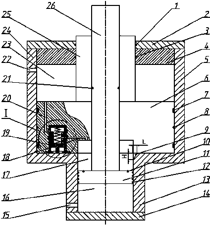
[0028] The utility model relates to a speed-changing double-piston serial hydraulic cylinder. Such as figure 1 As shown, the hydraulic cylinder includes a large end cover 2, a guide sleeve 4, a cylinder body 24, a large piston 6, a large piston rod 25, a small piston 11, a small piston rod 26, a small end cover 14 and a quick shut-off valve 19.

[0029] Such as figure 1 As shown, the cylinder body 24 is an integral body composed of the large cylinder body 5 and the small cylinder body 13. The end portion of big cylinder body 5 is fixedly equipped with large end cap 2, and the end portion of small cylinder body 13 is fixedly equipped with small end cap 14, and guide sleeve 4 is closely attached to large end cap 2 and is concentrically fixed in large cylinder body 5. The large cylinder body 5 has a first oil port 22 which is close to the guide sleeve 4 ; the small cylinder body 13 has a second oil port 15 which is close to the small end cap 14 . Four triangular grooves 9 are ...

Embodiment 2

[0038] The utility model relates to a speed-changing double-piston serial hydraulic cylinder. Present embodiment except following technical parameters, all the other are with embodiment 1:

[0039] The axial length H of described triangular groove 9 is 7 ~ 8mm, and the radial length L of triangular groove 9 is 5 ~ 6mm; The isosceles included angle of the projection is 60-75°, and the vertical plane is a plane perpendicular to the radial direction of the triangular groove 9 .

[0040] The groove width of the pressure equalizing groove 12 is 0.6~0.8mm, and the groove depth is 0.8~1.0mm.

[0041] The working process of this embodiment:

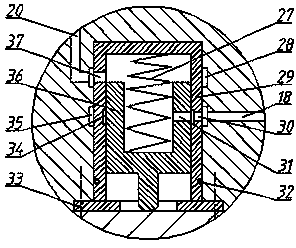
[0042] When the hydraulic oil enters the large piston rod cavity 23 from the first oil port 22, the large piston 6 moves inward to the bottom of the large cylinder 5, and the ejector rod of the valve core 36 is reacted by the bottom of the large cylinder 5, and the valve The core 36 compresses the spring 27, so that the hydraulic oil in the ro...


PUM


Abstract

The invention particularly relates to a variable speed double-piston series-connection hydraulic cylinder. According to the technical scheme, the end of a large piston rod (25) extends out of a guide sleeve (4) and a large end cap (2), the other side of a large piston (6) is concentrically provided with a small piston hole, the aperture of the small piston hole is equal to the outer diameter of a small piston (11), the depth of the small piston hole is equal to the thickness of the small piston (11), the large piston (6) and the large piston rod (25) are concentrically provided with small piston rod through holes, and a small piston rod (26) penetrates through the small piston rod through holes. The side face of the large piston (6) on the same side with the small piston holes is provided with a valve base hole, the hole wall of the valve base hole is sequentially provided with a first annular oil groove (28) and a second annular oil groove (35) from inside to outside, the first annular oil groove (28) is communicated with a rod cavity (23) of the large piston rod through a first oil channel (20), the second annular oil groove (35) is communicated with the small piston hole of the large piston (6) through a second oil channel (18), and a quick stop valve (19) is fixed to the inside of the valve base hole. The variable speed double-piston series hydraulic cylinder has the advantages of being simple in switch, saving energy, lowering cost, and being convenient to maintain and stable in switch process.

Description

technical field [0001] The invention belongs to the technical field of hydraulic cylinders. It specifically relates to a speed-changing double-piston serial hydraulic cylinder. Background technique [0002] At present, in hydraulic equipment, the speed of hydraulic components such as hydraulic cylinders and hydraulic motors is one of the important working performances of the hydraulic system. The mouth is used to adjust the flow rate and achieve the purpose of adjusting the speed. However, these throttle valves or speed regulating valves are generally installed on the main oil circuit, bypass oil circuit or return oil circuit of the hydraulic system to form a throttling and speed regulating system. No matter where it is installed, the hydraulic oil will have pressure loss through the throttle valve. , this loss will be converted into heat energy, increasing the temperature of the hydraulic oil. If the oil temperature is too high, the hydraulic oil will deteriorate, reduce...

Claims


Application Information

Patent Timeline
Patent Type & Authority Applications(China)
IPC IPC(8): F15B15/17
Inventor 湛从昌陈奎生龚云蒋俊陈新元吴凛
Owner WUHAN UNIV OF SCI & TECH
Why Eureka
Try Eureka