Mine gallery driving cut blasting method

A technology for level entry and mines, which is applied in the field of excavation and blasting of mine entry and entry, which can solve the problems of affecting the efficiency of excavation, small space, and many charges in charging holes, and achieve the effect of saving explosives and production excavation costs

Inactive Publication Date: 2014-06-18
JIANGXI RARE EARTH & RARE METALS TUNGSTEN GRP HLDG CO LTD
View PDF9 Cites 8 Cited by
  • Summary
  • Abstract
  • Description
  • Claims
  • Application Information

AI Technical Summary

Problems solved by technology

When cutting and blasting, firstly, due to the effect of rock clamping, the space is small, and the broken rocks after blasting cannot be completely thrown out of the cutting frame, and sometimes crowding occurs, which affects the blasting effect; There are a lot of charges in the gun hole, and the cost is high, but the cutting effect is poor, resulting in a relatively low utilization rate of the blast hole, and the cutting depth is limited, which affects the tunneling efficiency

Method used


Image

  • Mine gallery driving cut blasting method
  • Mine gallery driving cut blasting method

Examples


Embodiment 1

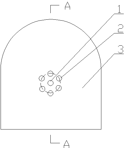
[0017] Example 1 figure 1 , 2 Shown: A method of cutting and blasting for tunnel excavation in mines, which includes drilling a cutting blast hole perpendicular to the work surface 3 in the center of the tunnel excavation work surface. Its characteristics are:

[0018] ① Drill a central blast hole 1 perpendicular to the working surface 3 in the center of the tunnel driving working surface 3, drill 6 evenly distributed perimeters on a circle with the central blast hole 1 of the working surface 3 as the center and a radius of 10 cm Hole 2

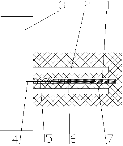
[0019] ② The depth of the central blasthole 3 is 30cm greater than the depth of the surrounding peripheral holes 2 and the depths of the surrounding peripheral holes 2 are equal. The central blasthole 1 and the surrounding peripheral holes 2 are parallel to each other;

[0020] ③ The center blast hole 1 is a charge hole, and the surrounding peripheral holes 2 are hollow holes;

[0021] ④ After the central blast hole 1 is filled with the explosive rol...


PUM


Abstract

The invention relates to a mine gallery driving cut blasting method which includes the steps that a center blasting hole perpendicular to a working plane is drilled in the center of the gallery driving working plane, five to eight evenly-distributed peripheral holes are drilled in the circumference with the center blasting hole of the working plane as the circle center and the radius ranging from 9 cm to 12 cm, the depth of the center blasting hole is 20 cm-40 cm larger than the depths of the surrounding peripheral holes, the depths of the surrounding peripheral holes are equal, the center blasting hole and the surrounding peripheral holes are parallel to each other, the center blasting hole serves as a powder filling hole, the surrounding peripheral holes are hollow holes, hole openings are packed with stemming after the center blasting hole is filled with an explosive reel and a blasting cap connected with an explosion conducting pipe, when explosives in the center blasting hole are detonated, the hollow peripheral holes serve as free surfaces and compensation space, and the aim of breaking and throwing rock in a cutting frame is achieved; due to the fact that the depth of the center blasting hole is 20 cm-40 cm larger than the depths of the surrounding peripheral holes, the rock throwing force is strengthened, the rock is completely thrown out, and the cutting effect is improved and guaranteed.

Description

Technical field [0001] The invention relates to a mine roadway or tunnel excavation technology, in particular to a mine roadway excavation and blasting method. Background technique [0002] Most of the underground metal mines in my country are small and medium-sized mines. Most of the tunnels excavated are of small section. The tunneling method is shallow cut blasting. Because of the small section, the rock clamp is large, the blast hole diameter is small, and the one-time blast hole The depth is limited, and the blast hole utilization rate is generally within 85%, and 15% of the blast holes are not used, which affects the tunneling effect and efficiency. In the case of restricted aperture and cross-section, the quality of the blasting effect and the utilization rate of blast holes depend on the quality of the cutting effect; the failure of the cutting blasting will lead to failure of the blasting in the tunneling, which will affect the entire tunneling Circulation and excavation...

Claims


Application Information

Patent Timeline
Patent Type & Authority Applications(China)
IPC IPC(8): F42D1/00F42D3/04
Inventor 文柏茂昌海军齐永茂谭辉琪
Owner JIANGXI RARE EARTH & RARE METALS TUNGSTEN GRP HLDG CO LTD
Why Eureka
Try Eureka