Demodulation circuit of non-contact IC card

A demodulation circuit, non-contact technology, applied in the field of non-contact IC card demodulation circuit, can solve the problems of small drive current, pull down, affect FDT, etc., and achieve the effect of increased drive capacity

Active Publication Date: 2014-06-18
SHANGHAI HUAHONG GRACE SEMICON MFG CORP
View PDF3 Cites 9 Cited by
  • Summary
  • Abstract
  • Description
  • Claims
  • Application Information

AI Technical Summary

Problems solved by technology

[0014] like figure 1 As shown, the second input terminal of the comparator 106 is biased by the bias circuit 107. When the groove signal in the input modulated signal arrives, the input signal VREF3 needs to be pulled low. When the groove signal At the end, VREF3 needs to return to normal potential from the potential that was just pulled down, and charge the capacitor 105. Since VREF3 must be smaller than VREF1 during the duration of "pause", the driving current of bias circuit 107 must be relatively small. For different field strengths, transmission rates, card readers, etc., when the groove signal ends, VREF3 may be at a lower level, resulting in too long a time to return to normal potential, which directly affects FDT

Method used


Image

  • Demodulation circuit of non-contact IC card
  • Demodulation circuit of non-contact IC card
  • Demodulation circuit of non-contact IC card

Examples


Embodiment Construction

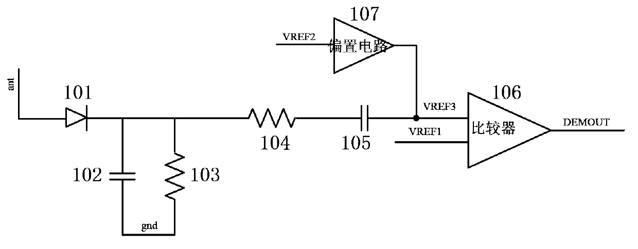
[0032] like Figure 4 shown is a schematic diagram of the demodulation circuit of the non-contact IC card in the embodiment of the present invention; in the demodulation circuit of the non-contact IC card in the embodiment of the present invention, the carrier frequency of the data transmitted from the card reader to the non-contact IC card is 13.56 MHZ, demodulation circuit includes:

[0033] Comparator 6, the first input terminal of the comparator 6 is connected to the first reference signal VREF1, the second input terminal of the comparator 6 is connected to the input signal VREF3, the input signal VREF3 is received by the contactless IC card. The modulated signal emitted by the card reader is the signal after detection and high-pass filtering; the output end of the comparator 6 outputs the demodulated signal DEMOUT.

[0034] The detection circuit unit for detecting the modulated signal includes a unidirectional diode 1, a first capacitor 2 and a first resistor 3; the positi...


PUM


Abstract

The invention discloses a demodulation circuit of a non-contact IC card. The demodulation circuit comprises a comparator, a bias circuit and an either-or switching circuit. The either-or switching circuit provides two reference signals of different amplitudes for the bias circuit. A driving control end of the bias circuit is connected with an output end of the comparator. The demodulation circuit outputs a demodulation signal to automatically select reference voltages input by the bias circuit and the driving capability of the bias circuit. Direct-current bias voltage at the input end of the comparator can be reduced and the driving capability can be increased upon the arrival a pause signal so that voltage at the input end of the comparator can be recovered quickly at the end of the pause signal to meet the requirement of FDT.

Description

technical field [0001] The invention relates to a semiconductor integrated circuit, in particular to a demodulation circuit of a non-contact IC card. Background technique [0002] Information is transmitted between the non-contact IC card and the card reader through radio frequency signals as carrier waves. The non-contact IC card itself has no power supply, and the power during its operation is provided by the radio frequency signal of the card reader, wherein the radio frequency signal of the card reader is 13.56MHz. When the card reader and the non-contact IC card transmit data to each other, the carrier is a 13.56MHz radio frequency carrier, and the signal transmission rates are 106kbits / s, 212kbits / s, 424kbits / s, and 848k bits / s. [0003] Among them, when the data is transmitted from the card reader to the non-contact IC card, the amplitude keying (ASK) method is used to modulate the signal, and the encoding method is synchronous and improved Miller encoding. When the...

Claims


Application Information

Patent Timeline
Patent Type & Authority Applications(China)
IPC IPC(8): G06K19/077
Inventor 唐成伟
Owner SHANGHAI HUAHONG GRACE SEMICON MFG CORP
Why Eureka
Try Eureka