Method and circuit for converting alternating-current sine wave signals into direct-current step wave signals

A technology of signal conversion and sine wave, applied in the direction of sine oscillation train generator, electrical components, etc., can solve the problems of low precision, high AD cost, complex circuit, etc., achieve the effect of simple circuit and improved circuit utilization efficiency

Inactive Publication Date: 2014-06-18
UNIV OF ELECTRONICS SCI & TECH OF CHINA
View PDF3 Cites 1 Cited by
  • Summary
  • Abstract
  • Description
  • Claims
  • Application Information

AI Technical Summary

Problems solved by technology

In the field of electronic circuit design, the step wave is a commonly used analog signal. The sine wave to the step wave can be generated by an AD (analog to digital converter) with a counter and a pulse generator, but this method is more complicated. AD higher cost
The traditional signal source adopts the pump-type ladder wave generation circuit, which has low precision and requires the pulse signal source to have a certain load capacity, so it can only be applied to occasions with low requirements

Method used


Image

  • Method and circuit for converting alternating-current sine wave signals into direct-current step wave signals
  • Method and circuit for converting alternating-current sine wave signals into direct-current step wave signals
  • Method and circuit for converting alternating-current sine wave signals into direct-current step wave signals

Examples


Embodiment Construction

[0028] Preferred embodiments of the present invention will be described in detail below with reference to the accompanying drawings, but the present invention is not limited to these embodiments. The present invention covers any alternatives, modifications, equivalent methods and schemes made on the spirit and scope of the present invention. In order for the public to have a thorough understanding of the present invention, specific details are described in detail in the following preferred embodiments of the present invention, but those skilled in the art can fully understand the present invention without the description of these details.

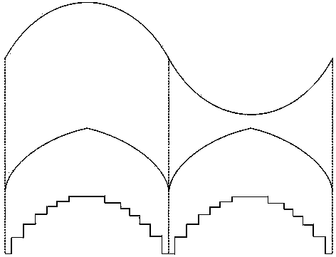
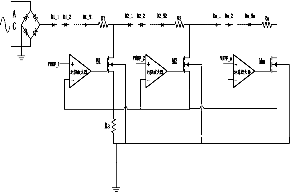
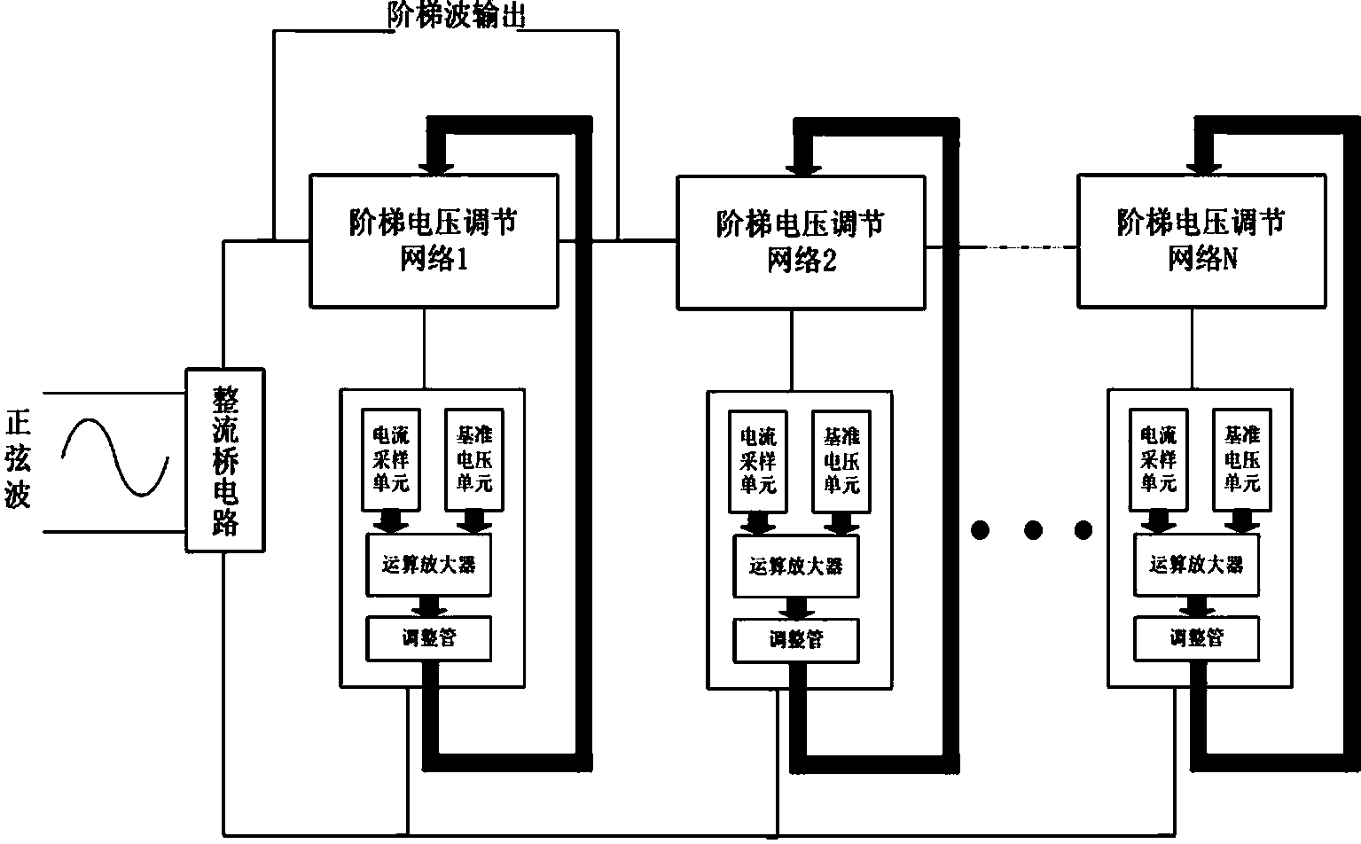
[0029] figure 1 It is a functional block diagram of a sine wave to step wave conversion circuit of the present invention. This embodiment includes a rectifier bridge circuit, a ladder voltage regulation network, a current sampling unit, a reference voltage unit, an operational amplifier and an adjustment tube.

[0030] The rectifier bridg...


PUM


Abstract

The invention discloses a method and circuit for converting alternating-current sine wave signals into direct-current step wave signals. The method comprises the steps that (1) the alternating-current sine wave signals are rectified into direct-current head signals; (2) the head wave signals are transmitted into a plurality of voltage adjusting devices with different amplitudes, and are divided into multiple stages of voltage signals; (3) the voltage signals are respectively transmitted into a constant current device, voltage signal waves form flat-topped waves, all flat-topped wave voltage signals are connected in sequence, and the direct-current step wave signals are obtained. The circuit comprises a rectifier bridge circuit, the voltage adjusting devices and a plurality of constant current control devices, the rectifier bridge circuit rectifies the alternating-current sine wave signals into the direct-current head wave signals, the voltage adjusting devices are connected in parallel to form a network, the voltage adjusting set values of the voltage adjusting devices are different, the direct-current head wave signals are divided into the multi-stage signals with different amplitudes, the number of the constant current control devices is equal to that of the voltage adjusting devices, the constant current control devices are correspondingly connected with the voltage adjusting devices respectively, and used for controlling the currents of the voltage adjusting devices to be kept constant, and the output signals of the voltages adjusting devices are made to be the flat-topped waves. All the flat-topped wave signals are connected in sequence, and the direct-current step wave signals are formed.

Description

technical field [0001] The invention belongs to the field of electronic circuits, and relates to a method and a circuit for converting an AC sine wave signal into a DC ladder wave signal. Background technique [0002] In the electronic measurement and automatic control system, the sine wave is a very important analog signal and has a wide range of applications. Converting the sine wave into a step wave can be treated as a digital signal. The staircase wave is a signal whose value does not change continuously with time, and its value is discrete. The staircase wave generated by the staircase wave signal generator can be used as a timing control signal and a multi-pole potential reference signal. [0003] In some practical applications, the step wave has been widely used due to its digital characteristics. For example, the step wave signal source is often required as the transistor base signal source in the transistor characteristic test. In the field of electronic circuit de...

Claims


Application Information

Patent Timeline
Patent Type & Authority Applications(China)
IPC IPC(8): H03B25/00H03K3/80
Inventor 张徐亮彭瑞敏张建刚陈金虎王朋何松柏
Owner UNIV OF ELECTRONICS SCI & TECH OF CHINA
Why Eureka
Try Eureka