A ladder wave generating circuit

A technology for generating circuits and ladder waves, applied in pulse generation, electrical components, pulse technology, etc., can solve the problems of complex circuit structure, difficulty of ladder waves, limited application, etc., and achieve the effect of simple circuit structure and improved circuit utilization efficiency

Inactive Publication Date: 2016-05-11
UNIV OF ELECTRONICS SCI & TECH OF CHINA
View PDF4 Cites 0 Cited by
  • Summary
  • Abstract
  • Description
  • Claims
  • Application Information

AI Technical Summary

Problems solved by technology

It can be seen that this solution is realized by integrated operational amplifiers or transistors. Although it is simple, it has obvious disadvantages: it is very difficult to generate a ladder wave whose level can be adjusted at will, and all circuits such as square wave generators and comparators need to be rebuilt Setting and adjustment will cause the circuit structure to become complicated
The second option is as Figure II As shown, including clock signal generator, counter, CPU and digital-to-analog converter, it is mainly realized by programmable devices to control the generation of ladder waves. Compared with the first scheme, this scheme can obtain flexible and changeable waveforms, but This solution requires programming, which limits its application occasions. On the other hand, the high-speed processor costs more, which further limits its application.

Method used


Image

  • A ladder wave generating circuit
  • A ladder wave generating circuit
  • A ladder wave generating circuit

Examples


Embodiment

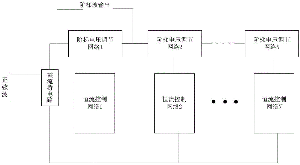
[0029] like Figure 5 As shown, the AC sine wave AC is rectified by the rectifier bridge and becomes a steamed bun wave. When the voltage is zero, the m ladder voltage regulation network has no current, the current flowing through the sampling resistor Rs is zero, the voltage on the sampling resistor is zero, and the voltage fed back to the negative input terminals of the m operational amplifiers is zero, and the output of the operational amplifier is zero. Forward saturation voltage, the m MOS transistors M1M2...Mm are fully turned on. When the voltage rises to the voltage at which the N1 diodes of the first ladder voltage regulation network are turned on, the first ladder voltage regulation network is turned on, and a current flows through the sampling resistor. The voltage continues to increase, and the current increases. Due to the clamping effect of the op amp, the current is constant at VREF_1 / Rs. The ladder output voltage is:

[0030] V=N1*Vt+R1*VREF_l / Rs

[0031] V...


PUM


Abstract

The invention relates to electronic circuit technology, in particular to a ladder wave generating circuit. The rectifier bridge circuit of the present invention is characterized in that it also includes a plurality of ladder voltage regulation networks and a plurality of constant current control networks, the rectifier bridge circuit is connected with the ladder voltage regulation network and the constant current control network, and the ladder voltage regulation The number of network and constant current control network is equal to one corresponding connection. The beneficial effect of the invention is that it can generate a ladder wave with any order and adjustable step voltage, and at the same time, the circuit structure is simple, there is no digital logic control, and no programming is required, which can effectively improve the utilization efficiency of the circuit. The invention is especially suitable for the ladder wave generating circuit.

Description

technical field [0001] The invention relates to electronic circuit technology, in particular to a ladder wave generating circuit. Background technique [0002] At present, in the field of electronic circuit design, the staircase wave is a commonly used analog signal. The traditional ladder wave generator generally has the following two schemes: the first scheme is as follows figure 1 As shown, it consists of a square wave generator, a differential circuit, a limiting circuit, an integral accumulation circuit, an electronic switch circuit, a comparator and an oscillation circuit. Both have sharp pulse waveforms. At this time, to only take the sharp pulse above, it is necessary to filter out the lower half of the waveform through the limiter circuit. When these pulses pass through the integration and accumulation circuit, a sharp pulse is accumulated to a fixed value, and the same value will be increased when the next pulse arrives, so the output forms a staircase waveform....

Claims


Application Information

Patent Timeline
Patent Type & Authority Patents(China)
IPC IPC(8): H03K4/02
Inventor 李泽宏张建刚肖栩弋才敏李蜀一汪榕
Owner UNIV OF ELECTRONICS SCI & TECH OF CHINA
Why Eureka
Try Eureka