Tunnel type hot air circulation tunnel furnace

A hot air circulation, tunnel-type technology, applied in the field of tunnel furnaces, can solve the problems of uneven color, unequal front and rear air volume, uncontrollable air temperature, etc., to achieve the effect of improving baking quality, convenient air volume, and uniform color

Active Publication Date: 2014-06-25
GUANGZHOU BAKE OVEN MACHINERY
View PDF12 Cites 14 Cited by
  • Summary
  • Abstract
  • Description
  • Claims
  • Application Information

AI Technical Summary

Problems solved by technology

The disadvantage is that due to the connection of the upper circulation duct and the lower circulation duct, the air volume of the circulation duct is small, the front and rear air volumes are not equal, and the air temperature is uncontrollable, which eventually leads to uneven baking color and limited improvement in the quality of baked food

Method used


Image

  • Tunnel type hot air circulation tunnel furnace
  • Tunnel type hot air circulation tunnel furnace
  • Tunnel type hot air circulation tunnel furnace

Examples


Embodiment Construction

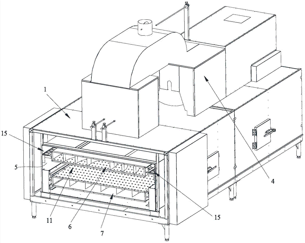
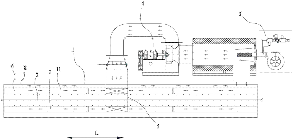
[0035] Such as Figure 1~3 The tunnel-type hot air circulation tunnel furnace shown includes a furnace body 1, a hot air circulation device, a conveyor belt 2 for transporting products to be baked, and a heating device (not shown in the figure) for heating products to be baked. The conveyor belt 2 runs through The furnace body 1 and the hot air circulation device include a hot air generator 3, a fan 4, a four-way joint 5, an upper wind box 6 and a lower wind box 7, and the hot wind generator 3 is connected to the fan 4 and is located outside the furnace body 1.

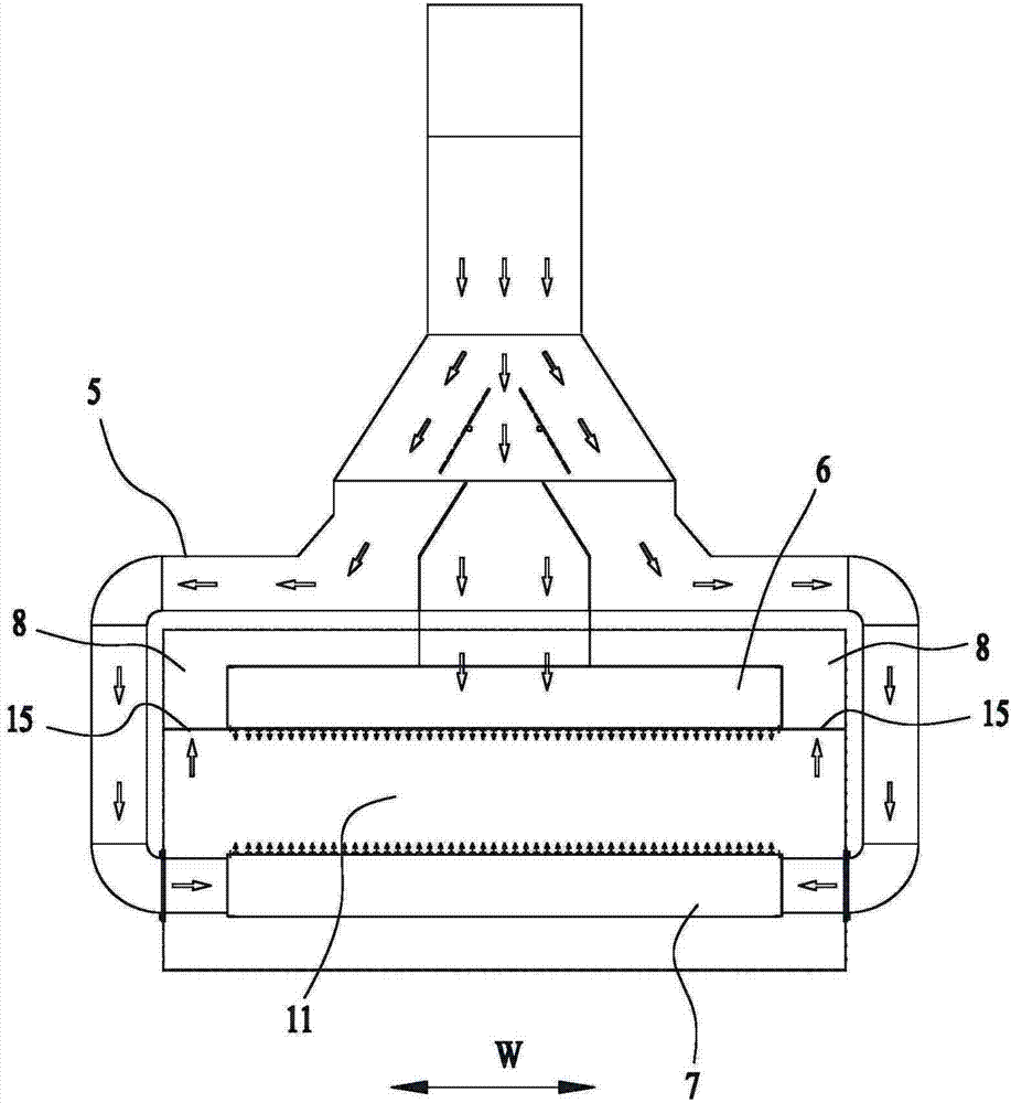
[0036] Such as Figure 10 As shown, the four-way joint 5 includes a horizontal air inlet shell 51 and two air inlet shells 52 vertically extending from the two ends of the air inlet shell 51. The top surface of the air inlet shell 51 has an inlet 511, and the air inlet shell 51 The bottom surface is provided with a first outlet 512, and the upper ends of the two sub-wind casings 52 are connected with the inlet 511, a...


PUM


Abstract

The invention discloses a tunnel type hot air circulation tunnel furnace. The tunnel type hot air circulation tunnel furnace comprises a furnace body, a hot air circulation device, a conveying belt and a heating device. The hot air circulation device comprises a hot air generator, a draught fan, a four-way connector, an upper air box and a lower air box. The four-way connector comprises a horizontal air inlet shell and two air distribution shells, wherein the two ends of the air inlet shell vertically extend to form the two air distribution shells. The top face of the air inlet shell is provided with an inlet. The bottom face of the air inlet shell is provided with a first outlet. The upper ends of the two air distribution shells are communicated with the inlet. The lower end of each air distribution shell is provided with a second outlet. The outlet of the draught fan is communicated with the inlet. The first outlet is communicated with the upper air box. The second outlets are communicated with the lower air box. The bottom of the upper air box is provided with a plurality of first air outlet holes. The top of the lower air box is provided with a plurality of second air outlet holes. A return air passage is arranged in the furnace body. The first air outlet holes and the second air outlet holes are connected with the hot air generator through the return air passage. According to the tunnel type hot air circulation tunnel furnace, hot air output by the hot air circulation device can be evenly and circularly led to products to be baked, and the air temperature, the air volume and the air speed can be controlled.

Description

[0001] technical field [0002] The invention relates to a tunnel furnace, in particular to a tunnel type hot air circulation tunnel furnace. Background technique [0003] Food gas baking tunnel furnaces (tunnel furnaces for short) are generally equipped with multiple flame-spray tubes for heating. As a heating device, each flame-spray tube is perpendicular to the length direction of the tunnel furnace. The upper interval is distributed, the conveyor belt runs through the furnace body of the tunnel furnace along the length direction of the tunnel furnace, and the flame-throwing tube bakes the products to be baked on the conveyor belt. [0004] In order to recycle the heat energy of the flame sprayed by the flame tube, most tunnel furnaces have added a hot air circulation device in the baking tunnel (between the flame tubes). The hot air circulation device consists of a circulating fan and a circulating air duct connected to the circulating fan through pipes. The circulating...

Claims


Application Information

Patent Timeline
Patent Type & Authority Applications(China)
IPC IPC(8): A21B1/26
Inventor 付文兵邵鸿飞唐德权
Owner GUANGZHOU BAKE OVEN MACHINERY
Why Eureka
Try Eureka